
Oil-gas cavity shell of scroll compressor

A technology for scroll compressors and oil-gas separation chambers, which is applied in the field of scroll compressors and can solve problems such as high production costs, many pipelines, and large space occupation

Pending Publication Date: 2021-06-11
NINGBO BAOSI ENERGY EQUIP
View PDF0 Cites 0 Cited by
  • Summary
  • Abstract
  • Description
  • Claims
  • Application Information

AI Technical Summary

Problems solved by technology

At present, the hosts of oil-injected scroll compressors on the market are all independently designed. To assemble a complete compressor, oil and gas tanks, combined valves, oil guide pipes and other components need to be assembled together. There are many pipelines and complex structures. Occupies a lot of space and high production costs

Method used


Image

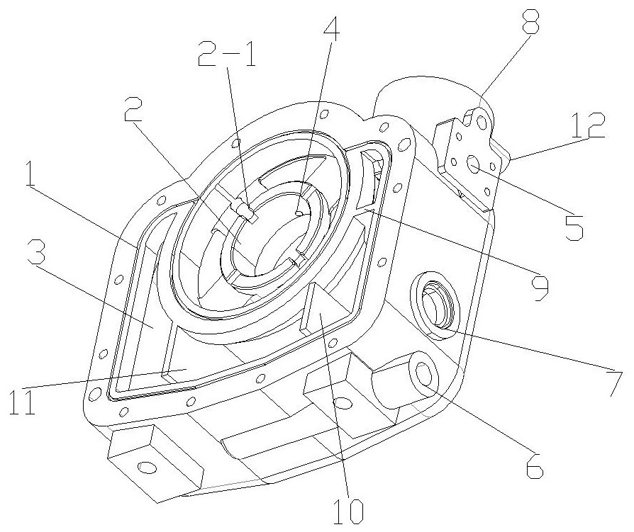
  • Oil-gas cavity shell of scroll compressor
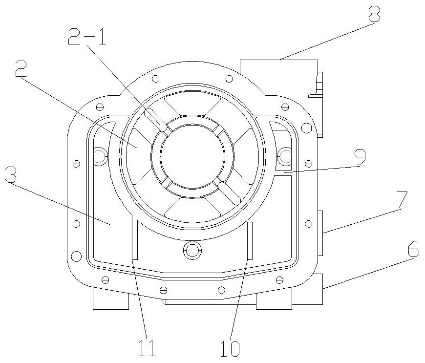
  • Oil-gas cavity shell of scroll compressor
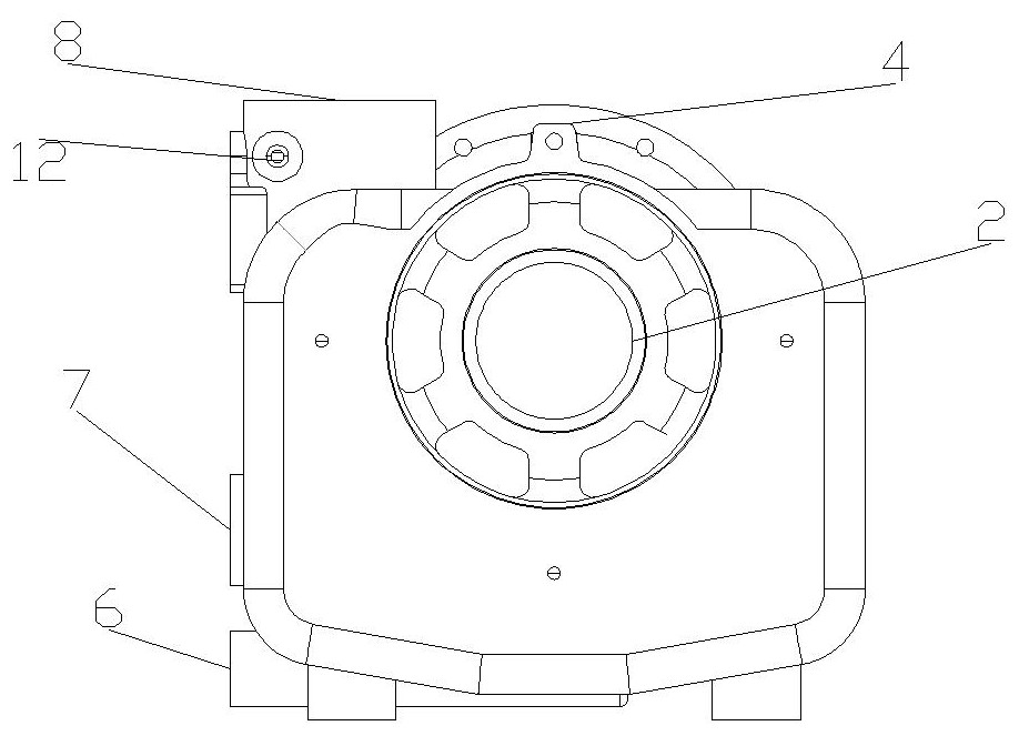
  • Oil-gas cavity shell of scroll compressor

Examples


Embodiment Construction

[0022] For a better understanding of the application, various aspects of the application will be described in more detail with reference to the accompanying drawings. It should be understood that these detailed descriptions are descriptions of exemplary embodiments of the application only, and are not intended to limit the scope of the application in any way. Throughout the specification, the same reference numerals refer to the same elements.

[0023] In the drawings, the thickness, size and shape of objects have been slightly exaggerated for convenience of illustration. The drawings are merely examples and are not strictly drawn to scale.

[0024] It should also be understood that the terms "comprising", "having", "comprising" and "comprising", when used in this specification, mean that the features, integers, steps, operations, elements and / or components exist, But it does not exclude the presence or addition of one or more other features, entities, steps, operations, ele...


PUM


Abstract

The invention provides an oil-gas cavity shell of a scroll compressor. The oil-gas cavity shell is provided with an orbiting scroll mounting part, an oil-gas separation cavity, an oil-gas separation core mounting hole, an oil return inlet, an oil return outlet and an exhaust port, the orbiting scroll mounting part is used for mounting an orbiting scroll, and the oil-gas separation core mounting hole is used for mounting an oil-gas separation core and is communicated with the oil-gas separation cavity; the oil return outlet and the exhaust port are both communicated with the oil-gas separation core mounting hole, the oil return outlet is used for guiding out oil separated by the oil-gas separation core, the exhaust port is used for exhausting gas separated by the oil-gas separation core, and the oil return inlet is communicated with the orbiting scroll mounting part; and due to the fact that the orbiting scroll mounting part, the oil-gas separation cavity, the oil-gas separation core mounting hole, the oil return inlet and the oil return outlet are all arranged on the oil-gas cavity shell, an external oil-gas tank, a combination valve, an oil guide pipe and other parts are avoided, a static disc shell of the scroll compressor is small and simple in structure, and assembling parts and connecting pipelines of the whole compressor are greatly reduced.

Description

technical field [0001] The present invention relates to the technical field of scroll compressors, and more specifically relates to an oil-gas chamber shell of a scroll compressor. Background technique [0002] In the compressor market, the scroll compressor is gradually replacing the traditional piston and rotary vane compressors. It has the characteristics of stable operation, high volumetric efficiency, high mechanical efficiency, long life and low failure rate, and is widely used in households. , office space, vehicles and other environments. The core component of the scroll compressor is a pair of intermeshing scrolls, one of which is a moving scroll and the other is a fixed scroll. The fixed scroll is always in a static state during the operation of the compressor, and the moving scroll The disc rotates very precisely relative to the fixed scroll to compress the gas. At present, the hosts of oil-injected scroll compressors on the market are all independently designed...

Claims


Application Information

Patent Timeline
Patent Type & Authority Applications(China)
IPC IPC(8): F04C29/00F04C29/02F04C29/04F04C18/02
CPCF04C18/0215F04C29/00F04C29/02F04C29/026F04C29/04F04C29/042F04C2240/30
Inventor 沈叶凯张炯焱吴常洪
Owner NINGBO BAOSI ENERGY EQUIP
Learn More