Middle cover structure for oil-gas separation of hydraulic retarder

A technology of hydraulic retarder and cover structure, which is applied in the field of auto parts, and can solve the problems of poor control accuracy of vehicle constant kinetic energy, reduced braking performance of hydraulic retarder, lack of working oil of retarder, etc. , to achieve the effects of easy processing, improved speed control accuracy, and high integration

Pending Publication Date: 2021-06-11
FUXIN DARE AUTOMOTIVE PARTS
View PDF0 Cites 1 Cited by
  • Summary
  • Abstract
  • Description
  • Claims
  • Application Information

AI Technical Summary

Problems solved by technology

Long-term use will cause the lack of working oil in the retarder, resulting in reduced braking performance or failure of the hydraulic retarder, polluting the environment and generating noise when exhausting
When the hydraulic retarder works at a constant speed, it is very important to control the stability of the air pressure. Only by adjusting the control air pressure through the solenoid valve will cause overshoot, which will easily cause the vehicle to shake and the speed control accuracy of the constant kinetic energy is poor.

Method used


Image

  • Middle cover structure for oil-gas separation of hydraulic retarder
  • Middle cover structure for oil-gas separation of hydraulic retarder
  • Middle cover structure for oil-gas separation of hydraulic retarder

Examples


Embodiment Construction

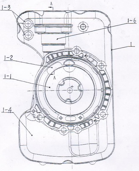
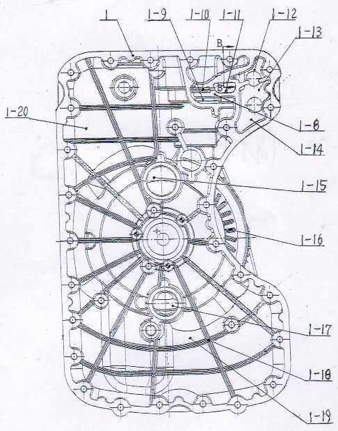
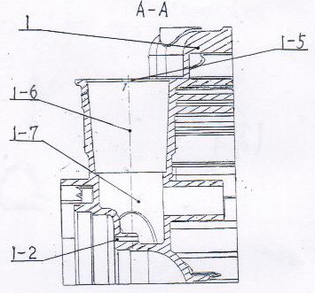
[0012] Examples, see attached Figure 1~4 , the front side of the middle cover 1 in the middle cover structure of the oil-gas separation of the hydraulic retarder is the side 1-4 connected with the front cover, and the rear side of the middle cover 1 is the side 1-20 connected with the rear cover. The middle of the side 1-4 connected with the front cover is the working chamber 1-1, the working chamber 1-1 is composed of a circular step hole and a large arc surface, and the step surface in the working chamber is provided with an exhaust hole 1-2. The upper end of the working chamber 1-1 is the oil-gas separation chamber 1-5, the upper end of the oil-gas separation chamber 1-5 is the oil-gas separator installation hole 1-6, the lower end is the working chamber oil-gas separation chamber 1-7, the working chamber oil-gas separation chamber 1 -7 communicates with the working chamber 1-1 through the exhaust hole 1-2, and there are two muffler installation holes 1-3 on the left side ...


PUM


Abstract

The invention belongs to automobile parts, and particularly relates to a middle cover structure for oil-gas separation of a hydraulic retarder. The front side face of a middle cover serves as a side face connected with a front cover, the rear side face of the middle cover serves as a side face connected with a rear cover, a working cavity is formed in the middle of the side face connected with the front cover, exhaust holes are formed in the step face of the working cavity, and a working cavity oil-gas separation chamber is arranged at the lower end of the working cavity and communicated with the working cavity through the exhaust holes; silencer mounting holes in the side face, connected with the front cover, of the back face of an exhaust cavity are communicated with a first pressure stabilizing chamber and a second pressure stabilizing chamber, an oil tank oil-gas separation area is arranged on the side face, connected with the rear cover, of the left side of the exhaust cavity, and the part, except the oil tank oil-gas separation area and the exhaust cavity, of the inner side of the joint between the middle cover and the rear cover serves as an oil tank; and a plurality of criss-cross reinforcing ribs II are arranged in the oil tank. The middle cover structure is simple in structure and high in integration level, can achieve oil-gas separation in the working cavity and the oil tank of the hydraulic retarder, and reduces the loss of working oil.

Description

technical field [0001] The invention belongs to auto parts, in particular to a middle cover structure for oil and gas separation of a hydraulic retarder. Background technique [0002] The hydraulic retarder is an auxiliary braking device, which converts all the kinetic energy of the vehicle into heat energy through the working chamber composed of the stator and the rotor, and dissipates the heat through the vehicle cooling system. When the hydraulic retarder is working, the temperature of the oil in the working chamber is high, which will produce atomized oil, which is easily lost through the intake and exhaust. When the hydraulic retarder is closed, the oil in the working chamber will quickly return to the fuel tank, and the air in the fuel tank will be quickly discharged. Due to the collision between the oil and the gas, the oil will be mixed into the air and discharged with the air. Long-term use will cause the lack of working oil in the retarder, resulting in reduced br...

Claims


Application Information

Patent Timeline
Patent Type & Authority Applications(China)
IPC IPC(8): F16D65/00F16D57/00
CPCF16D57/00F16D65/00F16D65/0006
Inventor 肖遥李文亮徐小东房思奇王忠伟
Owner FUXIN DARE AUTOMOTIVE PARTS
Why Eureka
Try Eureka