Supercharge Your Innovation With Domain-Expert AI Agents!

High-precision polarization-maintaining optical fiber loop curing method

A technology of polarization-maintaining optical fiber rings and optical fiber rings, which can be used in measuring devices, instruments, surveying and navigation, etc. It can solve problems such as complex structure, difficulty in UV light transmission, and affecting the performance of optical fiber rings, so as to reduce the impact and internal stress. Uniform distribution, the effect of improving temperature performance and vibration performance

Inactive Publication Date: 2021-06-11
CHINA ELECTRONICS TECH GRP NO 46 RES INST
View PDF6 Cites 3 Cited by
  • Summary
  • Abstract
  • Description
  • Claims
  • Application Information

AI Technical Summary

Problems solved by technology

However, UV light curing technology also has certain defects: the optical fibers in the optical fiber ring are closely arranged, and the adhesive is filled between the gaps of the optical fibers. lap performance

Method used


Image

  • High-precision polarization-maintaining optical fiber loop curing method
  • High-precision polarization-maintaining optical fiber loop curing method
  • High-precision polarization-maintaining optical fiber loop curing method

Examples


no. 1 example

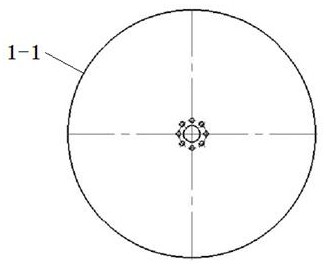
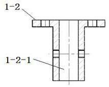
[0033] Step 1. Place one end of a 48-layer polarization-maintaining optical fiber ring 2 wound by an optical fiber with a diameter of 165 μm on the end surface of the metal disc 1-1 without bearing sleeve 1-2, and fasten the optical fiber on the metal circular cover plate 1-3 On the other end of the ring 2, place the optical fiber ring in the circular groove 1-3-1 of the metal circular cover plate 1-3, and pass the four bolts 1-4 through the circular end of the bearing sleeve 1-2 in turn 4 holes, 4 holes of the metal disc 1-1, fiber ring 2, 4 holes of the metal round cover 1-3 are screwed with nuts 1-5, and the fiber ring 2 is fixed on the rotary curing tray 1 superior;

[0034] Step 2. Fix the rotary curing tray 1 on the motor shaft through the shaft hole 1-2-1 of the raised end of the bearing sleeve 1-2 and the motor shaft, turn on the motor, and the motor shaft drives the rotary curing tray 1 to rotate at a constant speed, and the rotating speed Adjust to 10 rpm;

[0035]...

no. 2 example

[0038] Step 1. Put one end of a 64-layer polarization-maintaining optical fiber ring 2 wound by an optical fiber with a diameter of 165 μm on the end surface of the metal disc 1-1 without bearing sleeve 1-2, and fasten the metal circular cover plate 1-3 on the On the other end of the optical fiber ring 2, place the optical fiber ring in the circular groove 1-3-1 of the metal circular cover plate 1-3, and pass the four bolts 1-4 through the round surface of the bearing sleeve 1-2 in turn The 4 holes at the end, the 4 holes of the metal disc 1-1, the fiber ring 2, the 4 holes of the metal round cover 1-3 are screwed with the nuts 1-5, and the fiber ring 2 is fixed on the rotary curing tray 1 on;

[0039] Step 2. Fix the rotary curing tray 1 on the motor shaft through the shaft hole 1-2-1 of the raised end of the bearing sleeve 1-2 and the motor shaft, turn on the motor, and the motor shaft drives the rotary curing tray 1 to rotate at a constant speed, and the rotating speed Adj...


PUM


Abstract

The invention provides a high-precision polarization-maintaining optical fiber loop curing method, which aims at a polarization-maintaining optical fiber loop wound by an optical fiber using ultraviolet glue as solid glue, and comprises the following steps of placing the optical fiber loop on a rotary curing tray and rotating at a constant speed under the driving of a rotating shaft, focusing the light spot of the ultraviolet LED lamp on the side surface of the optical fiber loop to irradiate and cure the ultraviolet glue, and removing the rotary curing tray from the optical fiber loop subjected to primary rotary curing, and then irradiating the upper surface and the lower surface of the optical fiber loop by using an ultraviolet mercury lamp to further cure the optical fiber loop. According to the method, the ultraviolet solid glue is cured by adopting an ultraviolet lamp irradiation mode, and the processes of rotary curing of an ultraviolet LED lamp and secondary curing of an ultraviolet mercury lamp after bone removal are adopted in the curing process, so that complete curing of the ultraviolet solid glue between optical fibers of the optical fiber loop is better ensured, uniform distribution of the adhesive and uniform distribution of internal stress are realized, and the yield of the optical fiber loop is improved. And the influence on the optical fiber loop is reduced, so that the temperature performance and the vibration performance of the polarization-maintaining optical fiber loop are integrally improved.

Description

technical field [0001] The invention relates to the preparation of an optical fiber ring, in particular to a curing method for a high-precision polarization-maintaining optical fiber ring. Background technique [0002] In 1976 v. Vali and R. W. Since Shorthill proposed the concept of fiber optic gyroscope, the research of fiber optic gyroscope has been developed rapidly, and it has become one of the most important achievements in the field of fiber optic sensing. Based on the Sagnac effect, the fiber optic gyro is a new type of fiber optic angular rate sensor. It has the advantages of all solid state, no rotating parts and friction parts, long life, large dynamic range, instant start, simple structure, small size and light weight. It has been widely used in the fields of aviation, aerospace, navigation, weapons, robot control, oil drilling and radar. my country has vigorously developed the fiber optic gyro technology as a key technology. The typical structure of a fiber o...

Claims


Application Information

Patent Timeline
Patent Type & Authority Applications(China)
IPC IPC(8): G01C25/00G01C19/72
CPCG01C25/00G01C19/722
Inventor 吴博吴迪王树宇庞璐刘军号沈一泽
Owner CHINA ELECTRONICS TECH GRP NO 46 RES INST
Features
  • R&D
  • Intellectual Property
  • Life Sciences
  • Materials
  • Tech Scout
  • Unparalleled Data Quality
  • Higher Quality Content
  • 60% Fewer Hallucinations
Learn More