
Wire galloping amplitude monitoring system based on microwave interference technology

A technology of wire galloping and microwave interference, applied in radio wave measurement systems, radio wave reflection/re-radiation, measurement devices, etc., can solve the problem of time-consuming and cost-intensive detection and repair of damaged devices, and is not suitable for long-term monitoring , Susceptible to environmental interference and other issues, to achieve huge economic and social benefits, great application and promotion value, and reduce the effect of power grid tripping rate

Inactive Publication Date: 2021-06-11
STATE GRID ZHEJIANG ELECTRIC POWER CO LTD QUZHOU POWER SUPPLY CO
View PDF3 Cites 2 Cited by
  • Summary
  • Abstract
  • Description
  • Claims
  • Application Information

AI Technical Summary

Problems solved by technology

[0004] (1) High construction cost
The point-by-point measurement deformation monitoring system needs to densely deploy sensors when monitoring large towers, and the workload in the field is heavy, resulting in high system costs and slow measurement speeds;
[0005] (2) Low degree of intelligence
System construction is time-consuming, and it will take a lot of time and cost to detect and repair damaged devices during operation;
[0006] (3) Low ability to work around the clock
However, laser equipment is as susceptible to environmental interference as measuring robots during long-distance measurement, and the current laser deflection meters are all point light source products, which are extremely expensive for multi-point measurement, and are not currently suitable for long-term monitoring.
High-definition cameras are easily affected by the weather, and are easily disturbed in poor light or rainy and snowy weather, making it difficult to achieve real-time monitoring throughout the day

Method used


Image

  • Wire galloping amplitude monitoring system based on microwave interference technology
  • Wire galloping amplitude monitoring system based on microwave interference technology
  • Wire galloping amplitude monitoring system based on microwave interference technology

Examples


Embodiment Construction

[0018] The following will clearly and completely describe the technical solutions in the embodiments of the present invention with reference to the accompanying drawings in the embodiments of the present invention. Obviously, the described embodiments are only some, not all, embodiments of the present invention. Based on the embodiments of the present invention, all other embodiments obtained by persons of ordinary skill in the art without making creative efforts belong to the protection scope of the present invention.

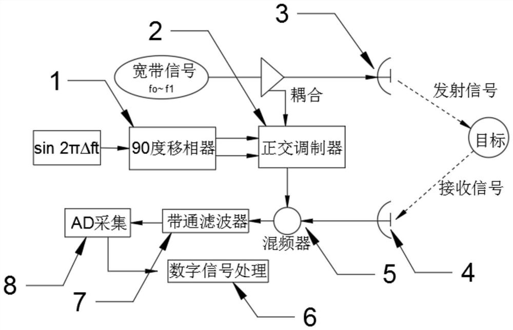
[0019] see figure 1 , a wire galloping amplitude monitoring system based on microwave interference technology in the figure, including a phase shifter 1, a modulator 2, a transmitting antenna 3, a receiving antenna 4, a mixer 5, a digital processor 6, and a filter 7 And collector 8, it is characterized in that: described transmitting antenna 3 signals are connected to Ethernet, and described Ethernet is connected with the modulator 2 that can adjust signal fre...


PUM


Abstract

The invention discloses a wire galloping amplitude monitoring system based on a microwave interference technology, which comprises a phase shifter, a modulator, a transmitting antenna, a receiving antenna, a mixer, a digital processor, a filter and a collector; the transmitting antenna is in signal connection with the Ethernet, the Ethernet is connected with the modulator capable of adjusting signal frequency offset, the modulator is in signal connection with a frequency mixer capable of mixing signals, the frequency mixer is in signal connection with a receiving antenna, the frequency mixer is in signal connection with a filter, the filter is in signal connection with a collector capable of collecting intermediate frequency signals, and the collector is in signal connection with a digital processor. According to the invention, timely early warning of pole and tower state operation evaluation can be achieved, the safety of a power transmission line is ensured, occurrence of power grid accidents is reduced, the trip-out rate of a power grid is reduced, reliable operation of the power grid is greatly improved, the technical problem of operation maintenance of the power grid in China is solved, and economic benefits and social benefits are huge.

Description

technical field [0001] The invention relates to the technical field of transmission line detection, in particular to a wire galloping amplitude monitoring system based on microwave interference technology. Background technique [0002] With the development of society and economy, more and more high-voltage transmission lines are gradually being surveyed, designed and constructed. Most of the high-voltage transmission lines are operated in the field and have been tested by harsh conditions for a long time. For many years, coastal areas have been severely damaged by typhoons. Line failures caused by typhoon disasters have accounted for more than 30% of the total trips. , causing accidents such as disconnection, flashover, and tower collapse, which brought major economic losses to the local power sector. In order to accurately monitor the towers and conductors of transmission lines, it is very important to help the power sector to find hidden dangers, troubleshoot faults, and ...

Claims


Application Information

Patent Timeline
Patent Type & Authority Applications(China)
IPC IPC(8): G01S13/42G01S7/41
CPCG01S13/42G01S7/41
Inventor 胡礼军程智吴蓉杨彬李承彬叶子豪吴广奇周博陈峰
Owner STATE GRID ZHEJIANG ELECTRIC POWER CO LTD QUZHOU POWER SUPPLY CO
Learn More