
Ceramic shell for laser detector, laser detector and preparation method

A technology of laser detectors and ceramic casings, applied in semiconductor devices, final product manufacturing, sustainable manufacturing/processing, etc., can solve the problems of poor device reliability, poor matching, inconvenient connection, etc., to meet the requirements of lightweight, guaranteed Mass, volume and mass reduction effects

Active Publication Date: 2021-06-11
THE 13TH RES INST OF CHINA ELECTRONICS TECH GRP CORP
View PDF5 Cites 1 Cited by
  • Summary
  • Abstract
  • Description
  • Claims
  • Application Information

AI Technical Summary

Problems solved by technology

[0005] The purpose of the present invention is to provide a ceramic shell for laser detectors, aiming to solve the problem of inconvenient connection and higher requirements for the loading platform of the ceramic shell with a conventional small sealing ring
[0006] The preparation method of the ceramic casing for laser detectors provided by the present invention aims to solve the problem of poor matching between large-sized metal components and large-cavity ceramic casings, resulting in poor device reliability

Method used

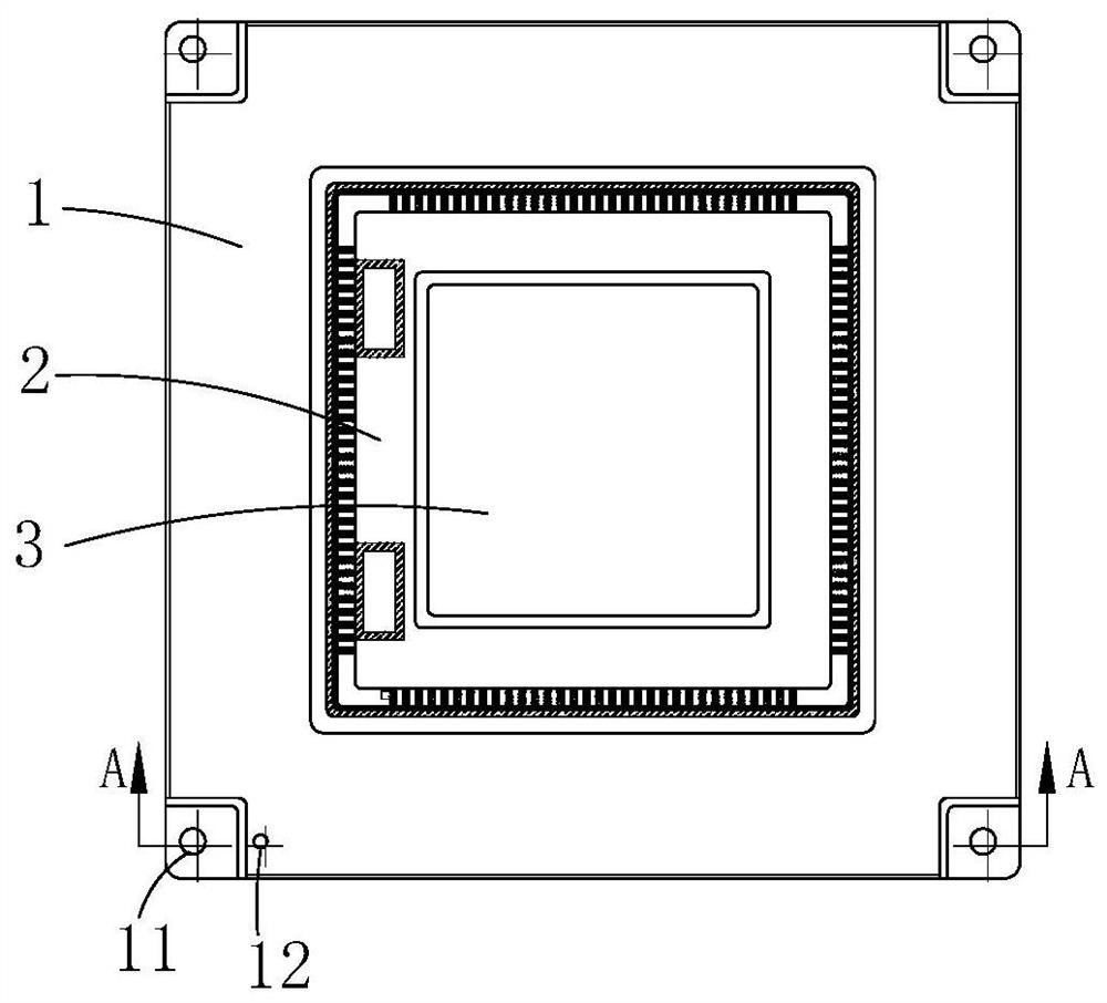
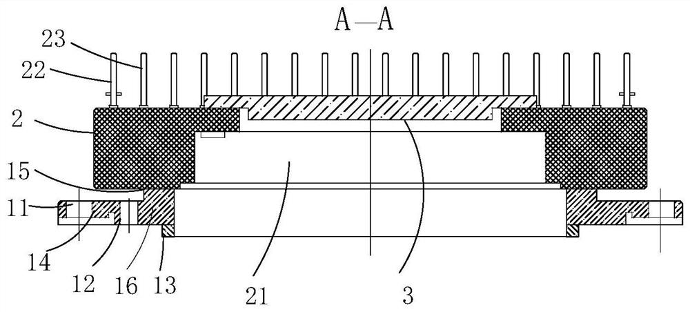
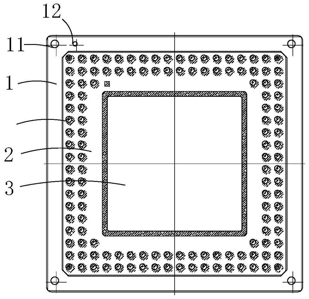

Image

  • Ceramic shell for laser detector, laser detector and preparation method
  • Ceramic shell for laser detector, laser detector and preparation method
  • Ceramic shell for laser detector, laser detector and preparation method

Examples


Embodiment Construction

[0030] In order to make the technical problems, technical solutions and beneficial effects to be solved by the present invention clearer, the present invention will be further described in detail below in conjunction with the accompanying drawings and embodiments. It should be understood that the specific embodiments described here are only used to explain the present invention, not to limit the present invention.

[0031] Please also refer to Figure 1 to Figure 3 , the ceramic casing for the laser detector provided by the present invention will now be described. The ceramic housing for the laser detector includes a ceramic base 2 and a flange 1, the ceramic base 2 has a packaging cavity 21; the flange 1 is arranged on the ceramic base 2, and the outer edge of the flange 1 protrudes from the The outer edge of the ceramic base 2; the protruding outer edge of the flange 1 has a connecting portion 14 for installation and fixing.

[0032] Compared with the prior art, the cerami...


PUM

PropertyMeasurementUnit
Thicknessaaaaaaaaaa

Abstract

The invention provides a ceramic shell for a laser detector, the laser detector and a preparation method of the ceramic shell, and belongs to the technical field of ceramic packaging. The ceramic shell comprises a ceramic base and a flange plate, and the ceramic base is provided with a packaging cavity; the flange plate is arranged on the ceramic base, and the outer edge of the flange plate protrudes out of the outer edge of the ceramic base; and the protruding outer edge of the flange plate is provided with a connecting part used for installation and fixation. According to the ceramic shell for the laser detector provided by the invention, the size of the flange plate is increased, and the connecting part used for fixed installation after packaging is arranged on the outer edge of the flange plate, so that the packaged device can be conveniently installed on a loading platform, and the requirement on the loading platform is reduced. According to the invention, the matching problem of the large-size metal component and the ceramic and the problems of residual stress and welding deformation compensation after high-temperature welding can be solved, good matching of the large-size metal component and the ceramic of a large cavity is achieved, the spatial resolution of a device and the imaging effect of an imaging system are guaranteed, and the reliability of signal transmission is improved.

Description

technical field [0001] The invention belongs to the technical field of ceramic packaging, and more specifically relates to a ceramic casing for a laser detector, a preparation method of the laser detector and the ceramic casing. Background technique [0002] Large-scale laser detectors are widely used in aviation and aerospace remote sensing imaging, and play an important role in the fields of environmental monitoring, resource census, topographic mapping and military reconnaissance. With the development of remote sensing application technology, people put forward higher and higher requirements for the integration degree of imaging chip and the scale of area array. However, the lead-out form of traditional metal packaged devices can only be drawn out through four sides or two sides. Such a package form determines the increase in the number of lead-out terminals, which greatly expands the package size of the metal case. [0003] As the volume, quality and cost of optical ima...

Claims


Application Information

Patent Timeline
IPC IPC(8): H01L31/0203H01L31/02H01L31/024H01L31/18
CPCH01L31/0203H01L31/024H01L31/18H01L31/02019Y02P70/50
Inventor 李航舟彭博高岭刘洋毕大鹏
Owner THE 13TH RES INST OF CHINA ELECTRONICS TECH GRP CORP
Learn More