Broadband reflectarray antenna based on single-layer paperclip element structure

A technology of reflectarray antenna and unit structure, which is applied in antennas, electrical components, waveguide horns, etc., can solve the problems of broadband performance and aperture efficiency, affect the performance of planar reflectarray antenna, and the phase range is less than 360°, etc., and achieve stability Good radiation characteristics, improved unit performance, and the effect of avoiding sudden change in size

Active Publication Date: 2022-05-17
NANJING UNIV OF SCI & TECH
View PDF3 Cites 0 Cited by
  • Summary
  • Abstract
  • Description
  • Claims
  • Application Information

AI Technical Summary

Problems solved by technology

[0003] However, most of the current existing designs need to add an additional air layer to achieve a gentle phase change, which increases the volume of the reflector array.
At the same time, in order to achieve reflection phase compensation within a 360° phase change period, there may be a size change between adjacent array elements
Since periodic boundary conditions are used in the unit simulation, the size of the surrounding unit structures is the same by default. This sudden change in size will cause errors in the unit phase compensation value, thereby affecting the performance of the planar reflectarray antenna.
The document "A Broadband Reflectarray Antenna Using Single-Layer Rectangular Patches Embedded With Inverted L-Shaped Slots" proposes a unit structure in which rectangular patches are embedded with inverted L-shaped slots, which can avoid the phase mutation problem between adjacent units, but its phase The range is less than 360°, while broadband performance and aperture efficiency need to be improved
To sum up, the current design methods of broadband reflection units are difficult to meet the existing application requirements

Method used


Image

  • Broadband reflectarray antenna based on single-layer paperclip element structure
  • Broadband reflectarray antenna based on single-layer paperclip element structure
  • Broadband reflectarray antenna based on single-layer paperclip element structure

Examples


Embodiment Construction

[0022] In order to make the purpose, technical solution and advantages of the present application clearer, the present application will be further described in detail below in conjunction with the accompanying drawings and embodiments. It should be understood that the specific embodiments described here are only used to explain the present application, and are not intended to limit the present application.

[0023] It should be noted that if there is a directional indication (such as up, down, left, right, front, back...) in the embodiment of the present invention, the directional indication is only used to explain the position in a certain posture (as shown in the accompanying drawing). If the specific posture changes, the directional indication will also change accordingly.

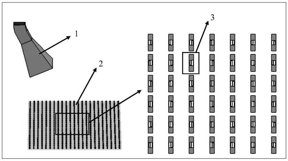
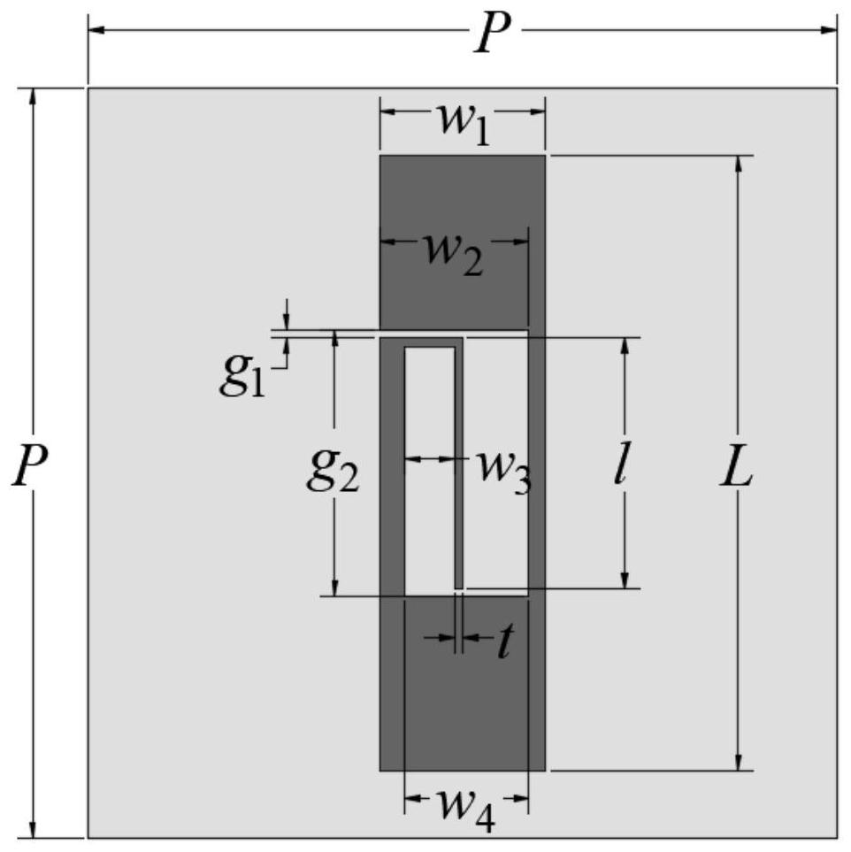
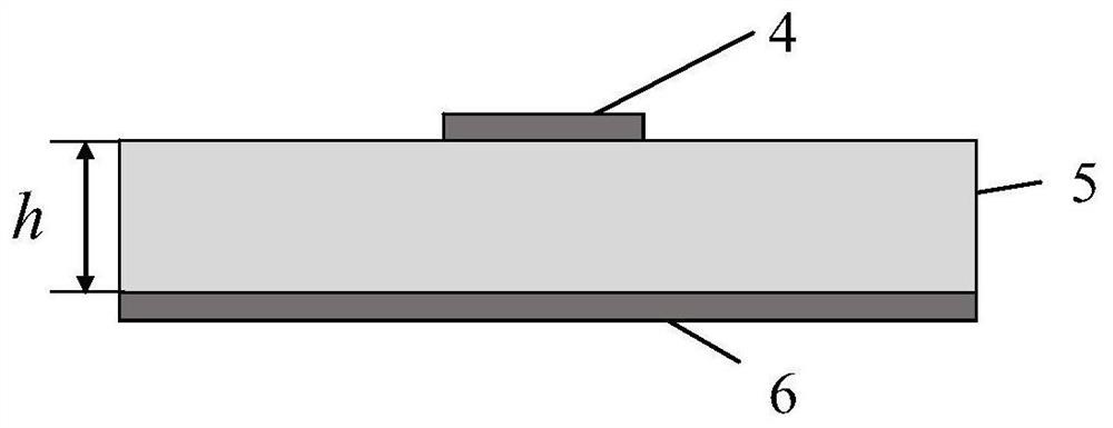
[0024] In one embodiment, combined with Figure 1 to Figure 3 , the present invention provides a broadband reflectarray antenna based on a single-layer paperclip unit structure, including a pyramidal h...


PUM

PropertyMeasurementUnit
thicknessaaaaaaaaaa
thicknessaaaaaaaaaa
dielectric lossaaaaaaaaaa

Abstract

The invention discloses a broadband reflective array antenna based on a single-layer paperclip unit structure, which includes a pyramidal horn antenna and a reflective array. The reflective array includes several reflective units, and each reflective unit includes a metal patch, a dielectric substrate and a metal connection. Floor, the metal patch is printed on the upper surface of the dielectric substrate, and the bottom of the dielectric substrate is provided with a metal grounding plate; the metal patch is a paper clip structure with an embedded inverted L-shaped metal arm, and the inverted L-shaped metal arm and the rectangular patch Leave a certain width between the inner edges on both sides. In the present invention, the outer dimensions of the rectangular patch of each reflective unit remain unchanged, and its phase can achieve a linear change of more than 360°. The planar reflective array antenna composed of reflective units can achieve a significant increase in gain bandwidth and aperture efficiency, and can be used during work. It presents stable and good radiation characteristics in the frequency band.

Description

technical field [0001] The invention belongs to the technical field of reflective array antennas, in particular to a broadband reflective array antenna based on a single-layer paperclip unit structure. Background technique [0002] With the rapid development of technologies such as radar target detection, satellite remote communication, and deep space exploration, the role of high-gain antennas in the field of modern communication is becoming more and more important. Compared with traditional high-gain antennas, planar reflectarray antennas have very broad development prospects due to their simple structure and easy processing, no need to design complex feeding networks, and flexible wide-angle electronic beam scanning. However, there is a significant disadvantage of the planar reflectarray antenna, which is its narrow bandwidth characteristic. Therefore, how to widen the bandwidth of the planar reflectarray antenna has become a topic of great research value and development...

Claims


Application Information

Patent Timeline
Patent Type & Authority Patents(China)
IPC IPC(8): H01Q15/14H01Q3/44H01Q3/30H01Q13/02
CPCH01Q15/145H01Q3/44H01Q3/30H01Q13/02
Inventor 郭璐郭美瑾冯文杰
Owner NANJING UNIV OF SCI & TECH
Why Eureka
Try Eureka