Conveyor system

A technology of conveying system and conveying line, applied in the field of conveying system, can solve the problems of large setting space and inability to set up spare lines, etc.

Active Publication Date: 2021-06-11
MURATA MASCH LTD
View PDF8 Cites 2 Cited by
  • Summary
  • Abstract
  • Description
  • Claims
  • Application Information

AI Technical Summary

Problems solved by technology

[0004] However, a large installation space is required in order to install a backup line corresponding to each of the two conveying lines
In factories etc. where the conveyor system is installed, there is only limited space and it is often not possible to install two backup lines

Method used


Image

  • Conveyor system
  • Conveyor system
  • Conveyor system

Examples


Deformed example 1

[0085] The description has been given by taking an example in which the rotary conveying unit 50 used in the first connecting line 17 and the second connecting line 19 in the above-described embodiment is provided so as to be capable of conveying the article F in both the third direction and the fourth direction. It is not limited to this.

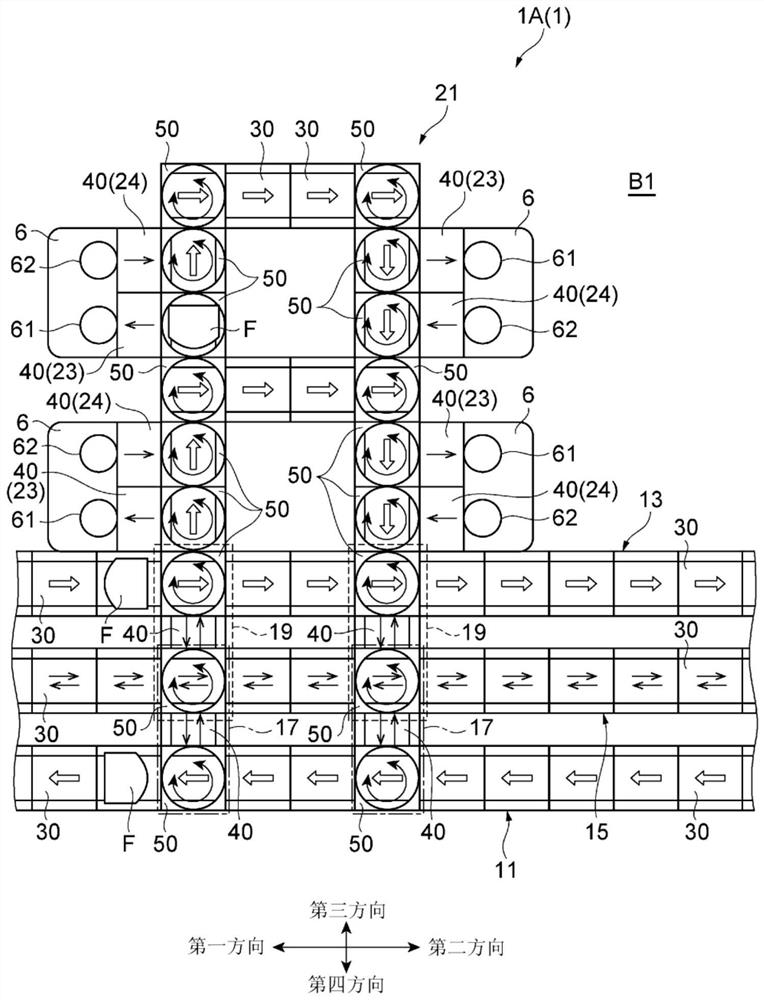
[0086] For example, as Figure 10 As shown, the first connecting line 17 may be configured to be provided with one or more second conveying units 40A capable of conveying only the carrying direction (third direction) of the articles F to the backup line 15, and one or more second conveying units 40A capable of conveying the articles F only in the direction from the back up line 15. The backup line 15 carries out the conveyance system 1D of the second conveyance unit 40B that conveys the article F in the conveyance direction (fourth direction).

[0087] In addition, for example, the second connection line 19 may be configured such that one...

Deformed example 2

[0090] In the conveyance system 1 ( 1A to 1D) of the above-described embodiment, an example in which the conveyance direction is relatively long has been described. Figure 11 As shown, the conveyance system 1E in which the 1st conveyance line 11, the 2nd conveyance line 13, the backup line 15, the 1st connection line 17, and the 2nd connection line 19 are arrange|positioned in a grid shape may be comprised. Moreover, the 1st conveyance line 11 and the 2nd conveyance line 13 face the carry-in port 71 which carries the article F into the conveyance system 1E, and the carry-out port 72 which carries out the article F from the conveyer system 1E.

[0091] In addition, in the said embodiment, although the example where abnormality occurred in the 1st conveyance unit 30 which comprises the 1st conveyance line 11 and / or the 2nd conveyance line 13 was mentioned and demonstrated, it is not limited to this. For example, as Figure 11 As shown, it may be used in the first direction or ...


PUM


Abstract

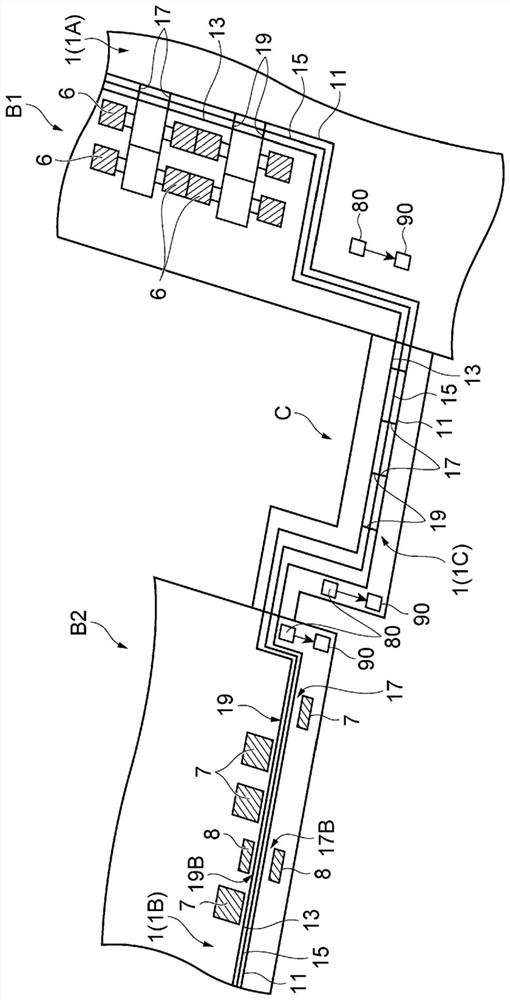
A conveyor system (1) comprises: a first conveyor line (11) that conveys an article (F) in a first direction; a second conveyor line (13) that is provided parallel to the first conveyor line (11), and conveys the article (F) in a second direction which is opposite to the first direction; a backup line (15) that is provided parallel to the first conveyor line (11) and the second conveyor line (13), and is provided so as to be switchable between a state in which the article (F) is conveyed in the first direction and a state in which the article (F) is conveyed in the second direction; a plurality of first connecting lines (17) that convey the article (F) between the first conveyor line (11) and the backup line (15); and a plurality of second connecting lines (19) that convey the article (F) between the second conveyor line (13) and the backup line (15).

Description

technical field [0001] The present invention relates to delivery systems. Background technique [0002] A conveyor belt apparatus is known as a conveying apparatus for conveying articles. For example, Patent Document 1 discloses a conveying system in which two conveying lines that convey articles in opposite directions in one direction are arranged in parallel along the width direction of a belt conveyor. In such a conveying system, for example, at the time of failure of the conveying line or during maintenance (hereinafter, these are collectively referred to as "conveying line abnormality".), it is often desirable to provide a backup line that can replace the conveyance of articles. In this case, for example, it is conceivable that a backup line is provided in each of the conveying lines for conveying articles in opposite directions. [0003] Patent Document 1: Japanese Patent Laid-Open No. 61-7133 [0004] However, in order to install a backup line corresponding to each...

Claims


Application Information

Patent Timeline
Patent Type & Authority Applications(China)
IPC IPC(8): B65G15/06B65G43/02B65G47/52
CPCB65G43/02B65G47/52B65G15/06B65G37/02H01L21/67715H01L21/67727B65G37/00B65G47/53B65G2207/14B65G2203/0266B65G2201/0297
Inventor 二见孝彦新井茂之
Owner MURATA MASCH LTD
Why Eureka
Try Eureka