Automatic material digging equipment for workshop processing

An automatic, workshop technology, used in metal processing equipment, metal processing, metal processing machinery parts, etc., can solve the problems of iron block damage, uneven manual operation force, easy to scratch hands, etc.

Active Publication Date: 2021-06-15
SHENZHEN JINGCHUANGHONG TECH
View PDF6 Cites 1 Cited by
  • Summary
  • Abstract
  • Description
  • Claims
  • Application Information

AI Technical Summary

Problems solved by technology

[0004] In order to overcome the shortcomings of manually using tools to dig out iron blocks, it is easy to scratch hands, and due to the uneven force of manual operation, it is easy to damage the iron blocks and increase the labor intensity of workers. The technical problem of the present invention is: to provide a Automatic digging equipment for workshop processing that does not hurt hands and reduces labor intensity

Method used


Image

  • Automatic material digging equipment for workshop processing
  • Automatic material digging equipment for workshop processing
  • Automatic material digging equipment for workshop processing

Examples


Embodiment 1

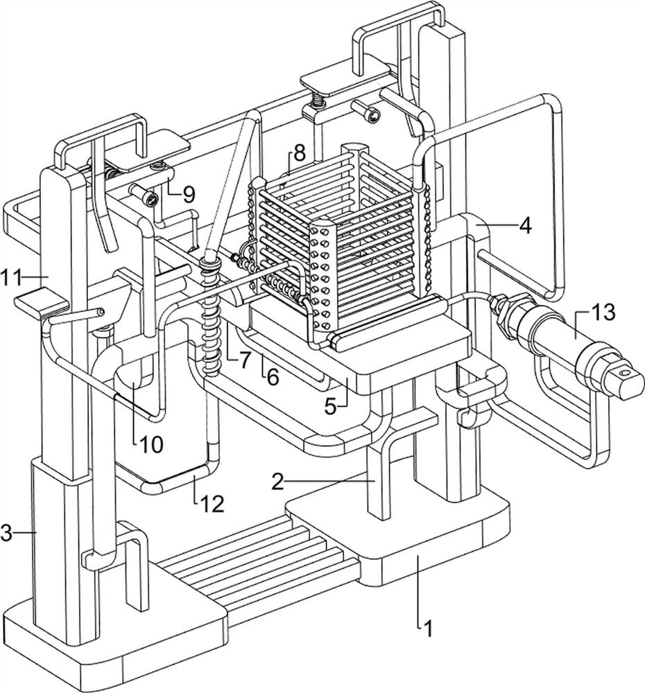
[0064] A kind of automatic digging equipment for workshop processing, such as figure 1As shown, it includes a first support plate 1, a first support frame 2, a telescopic sleeve 3, a fixed connecting frame 4, a second support plate 5, a second support frame 6, a third support plate 7, a pushing mechanism 8, and a Material mechanism 9, clamping mechanism 10 and auxiliary mechanism 11, first support plate 1 left and right sides are symmetrically provided with first support frame 2, first support plate 1 left and right sides are all provided with telescopic sleeve 3, telescopic sleeve 3 inner side and The outer side of the first support frame 2 is connected, and the middle of the front side of the telescopic sleeve 3 on both sides is symmetrically provided with a fixed connecting frame 4, and a second supporting plate 5 is arranged between the fixed connecting frames 4 on both sides, and the middle of the bottom of the second supporting plate 5 is left and right Both sides are pr...

Embodiment 2

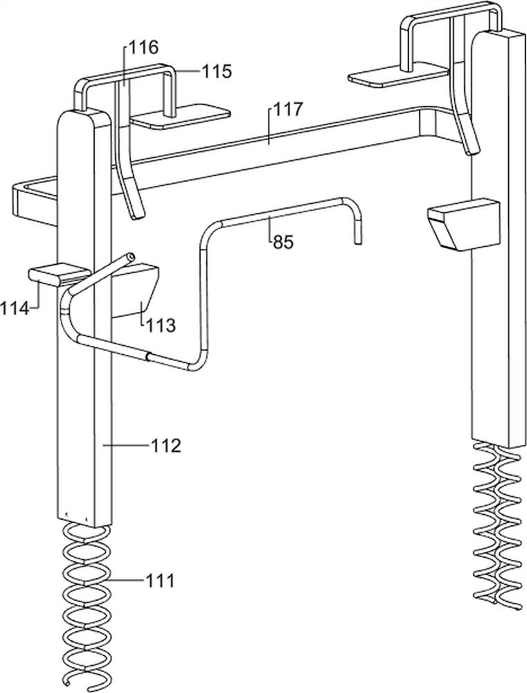
[0067] On the basis of Example 1, such as Figure 2-Figure 5 As shown, the pusher mechanism 8 includes a discharge frame 81, a third support frame 82, a pusher 83, a first spring 84 and a first cylindrical rod 85, and the upper side of the right side of the fixed engagement frame 4 right is provided with a release Material frame 81, the middle of discharging frame 81 left rear side is provided with the 3rd bracing frame 82, and the 3rd bracing frame 82 left side lower side sliding type is provided with pusher 83, and pusher 83 front left upper side is provided with first Cylindrical rod 85, the first spring 84 is wound around the rear side of the upper left part of the pusher 83, and the two ends of the first spring 84 are respectively connected with the first cylindrical rod 85 and the third support frame 82.

[0068] People put the iron block that needs to be pulled out into the feeding frame 81, and the iron block falls on the second support plate 5, and then people manuall...

Embodiment 3

[0076] On the basis of Example 2, such as Image 6 , Figure 7 As shown, it also includes a pressing mechanism 12, and the pressing mechanism 12 includes a round piece bar 121, a pressure-assisting block 122 and a sixth spring 123, and the fixed connecting frame 4 top right rear side sliding type on the left side is provided with a round piece bar 121, the round bar 121 cooperates with the lower pressure block 113 on the left side, the top of the right side of the round bar 121 is provided with an auxiliary pressing block 122, and the upper side of the right side of the round bar 121 is wound with a sixth spring 123, and the sixth spring 123 has two The ends are respectively connected with the round bar 121 and the fixed adapter frame 4.

[0077] When the lower pressing block 113 moves downward, the lower pressing block 113 drives the round bar 121 to move downward, and the sixth spring 123 is compressed, thereby driving the auxiliary pressing block 122 to move downward, and ...


PUM


Abstract

The invention relates to material digging equipment, in particular to automatic material digging equipment for workshop processing. According to the automatic material digging equipment for workshop machining, materials can be automatically dug out, hands are not hurt, and the labor intensity of workers is reduced. Automatic material digging equipment for workshop machining comprises: a first supporting plate and first supporting frames, wherein the first supporting frames are symmetrically arranged on the first supporting plate; telescopic sleeves which are arranged on the first supporting plate, wherein the inner sides of the telescopic sleeves are connected to the outer sides of the first supporting frames; fixed connecting frames which are symmetrically arranged between the telescopic sleeves on the two sides; a second supporting plate which is arranged between the fixed connecting frames on the two sides; and second supporting frames which are arranged in the middles of the bottoms of the second supporting plates. A pusher is manually pushed to move backwards, and a first spring is compressed, so that a first cylindrical rod is driven to move backwards, and an iron block is pushed to a third supporting plate to achieve the pushing effect.

Description

technical field [0001] The invention relates to a digging device, in particular to an automatic digging device for workshop processing. Background technique [0002] Iron has good ductility, electrical conductivity, and thermal conductivity. It belongs to magnetic materials and is an important material in industry. The iron and steel industry in my country is developing rapidly. Iron blocks are used to manufacture machines and tools. Machining refers to the processing of workpieces by a mechanical device In the process of changing the external dimensions or performance of the machine, various iron blocks are used in machining, and iron blocks are widely used. At present, in workshops and processing plants, tools are usually used to dig out iron blocks manually. , easy to scratch hands, and due to the uneven force of manual operation, it is easy to damage the iron block, which increases the labor intensity of workers. [0003] In view of the above-mentioned situation, we need ...

Claims


Application Information

Patent Timeline
Patent Type & Authority Applications(China)
IPC IPC(8): B23D79/00B23Q7/06B23Q3/06
CPCB23D79/00B23Q7/06B23Q3/06
Inventor 雷竹兰
Owner SHENZHEN JINGCHUANGHONG TECH
Why Eureka
Try Eureka