Mechanical arm auxiliary milling and shot blasting combined machining device

A compound processing and robotic arm technology, applied in the field of mechanical processing, can solve the problems of reducing the processing efficiency of parts, wasting time, wasting labor, etc.

Inactive Publication Date: 2021-06-15
UNIV OF JINAN
View PDF8 Cites 0 Cited by
  • Summary
  • Abstract
  • Description
  • Claims
  • Application Information

AI Technical Summary

Problems solved by technology

If the parts are shot peened after milling, it is necessary to manually move the parts from the milling machine to the s...

Method used


Image

  • Mechanical arm auxiliary milling and shot blasting combined machining device
  • Mechanical arm auxiliary milling and shot blasting combined machining device

Examples


Embodiment

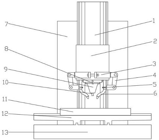
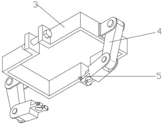
[0023] Examples of the present invention are figure 1 and figure 2 As shown, the present invention includes CNC axis Z-axis (1), milling machine spindle box (2), mechanical arm base (3), mechanical arm (4), fixture (5), shot blasting tube (6), shot blasting machine main body (7), milling machine spindle (8), milling cutter holder (9), milling cutter (10), CNC axis Y axis (11), CNC axis X axis (12), milling machine base (13). When the machine tool is working, the base of the mechanical arm (3) fixes the mechanical arm (4) on both sides of the spindle box (2) of the milling machine, and the operator adjusts the distance and Angle, and each side of the milling cutter is followed by a shot peening tube (6) to ensure that the shot peening tube (6) is always on the rear side of the milling cutter (10) and on one side for shot blasting when the milling cutter (10) is reciprocating. Finally, the machining work on the parts is completed simultaneously with the milling cutter (10). ...


PUM


Abstract

The invention relates to a mechanical arm auxiliary milling and shot blasting combined machining device and belongs to the technical field of machining. The mechanical arm auxiliary milling and shot blasting combined machining device comprises a milling machine whole body, a shot blasting machine whole body and a mechanical arm part. The invention aims to solve the problems of labor waste and low processing efficiency caused by factors such as replacement of a processing machine tool and disassembly, assembly and transportation by operators in the milling and shot blasting processes. By the adoption of the mechanical arm auxiliary milling and shot blasting combined machining device, disassembly, assembly and transportation in the part machining process are reduced, the part machining efficiency is effectively improved, and waste of labor force is avoided.

Description

technical field [0001] The invention relates to the technical field of mechanical processing, in particular to a mechanical arm-assisted milling and shot-peening composite processing device. Background technique [0002] In the aviation industry, the surface integrity of aviation parts directly affects its performance and service capability, especially the fatigue performance of parts. Therefore, after the milling process of the parts, the surface strengthening process is required to make them meet the performance. Shot peening technology significantly improves the fatigue performance of various aviation parts by changing the surface integrity of materials, and has the advantages of low cost, strong adaptability and convenient operation, and is widely used in the aviation field. If the parts are shot peened after milling, it is necessary to manually move the parts from the milling machine to the shot blasting machine. This process not only wastes labor, but also wastes time...

Claims


Application Information

Patent Timeline
IPC IPC(8): B23P23/04
CPCB23P23/04
Inventor 黄浩牛金涛王相宇仇文豪马欢欢郭璇蒋永乔阳
Owner UNIV OF JINAN
Why Eureka
Try Eureka