
Semi-automatic die cutting production line for silicone tubes

A semi-automatic mold and production line technology, applied in the direction of metal processing, etc., can solve the problems of hand injury of workers, easy impact of the second positioning rod, etc.

Active Publication Date: 2021-06-15
东莞市旭诚橡塑制品有限公司
View PDF5 Cites 0 Cited by
  • Summary
  • Abstract
  • Description
  • Claims
  • Application Information

AI Technical Summary

Problems solved by technology

[0006] In view of the above-mentioned related technologies, the inventor found the following defects in the long-term observation process: when the silicone tube 9 needs to be cut, the staff sets the silicone tube 9 on the jig 8, because both ends of the jig 8 are A positioning hole 811 is opened, and the staff places the jig 8 between the first installation column 611 and the second installation column 621, so that the first positioning rod 6121 is inserted into the positioning hole 811 at one end of the jig 8, and then passed through the second The three cylinders 622 drive the sliding cylinder 623 to slide towards the direction close to the jig 8, and the sliding cylinder 623 drives the second positioning rod 6231 to slide towards the direction close to the jig 8, so that the second positioning rod 6231 and the jig 8 are separated. The positioning hole 811 at one end is inserted and fitted, so that the jig 8 is fixed between the first mounting column 611 and the second mounting column 621; the third cylinder 622 drives the second positioning rod 6231 to slide toward the hand of the worker During the process, the second positioning rod 6231 is easy to hit the staff's hand, thus causing the staff's hand to be injured

Method used


Image

  • Semi-automatic die cutting production line for silicone tubes
  • Semi-automatic die cutting production line for silicone tubes
  • Semi-automatic die cutting production line for silicone tubes

Examples


Embodiment Construction

[0046] The following is attached Figure 2-8 This application is described in further detail.

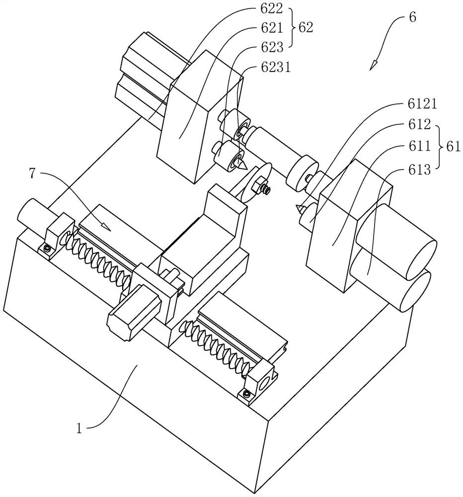
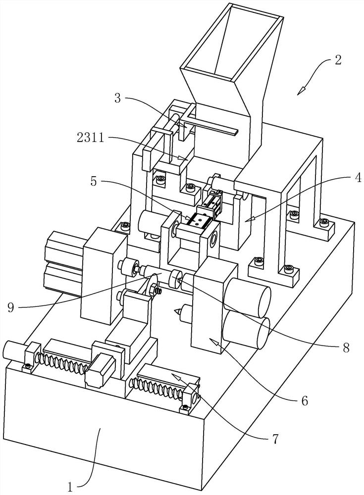
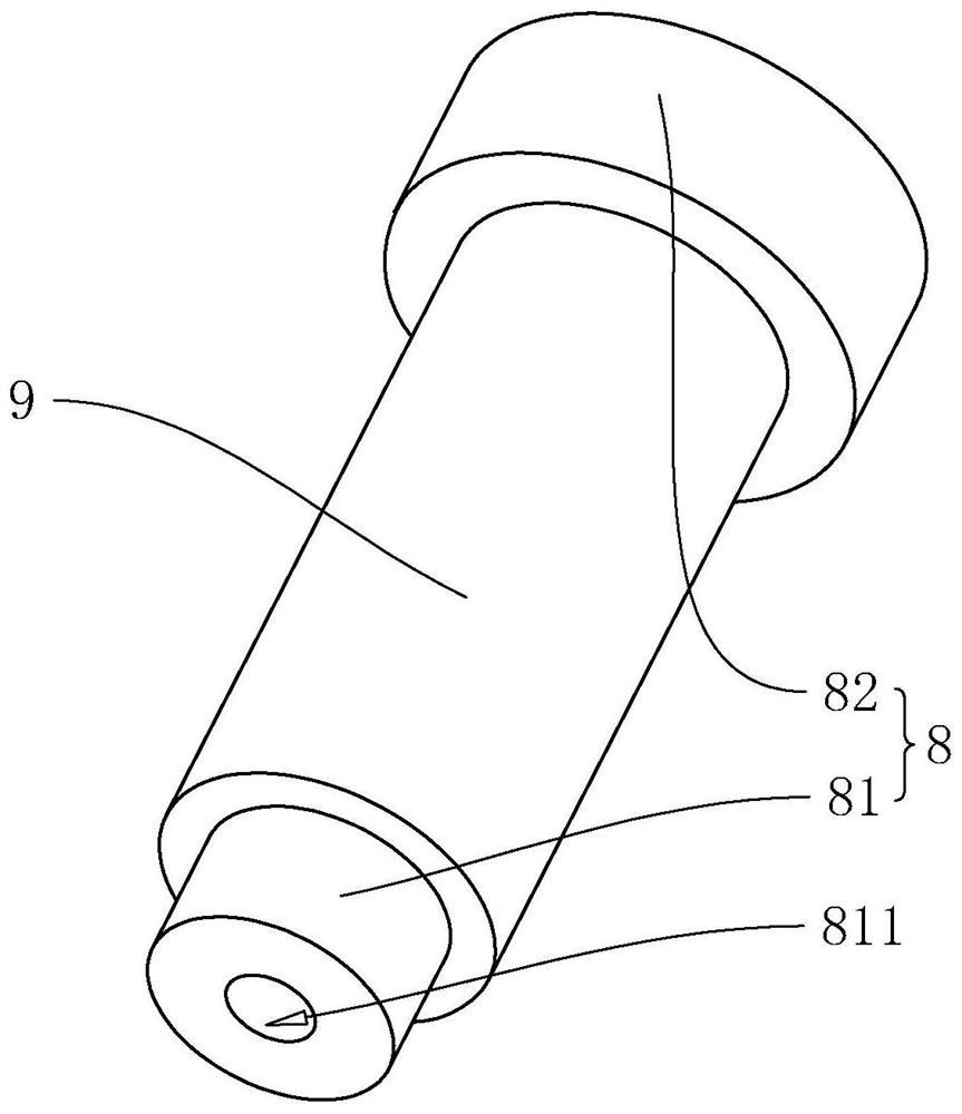
[0047] The embodiment of the present application discloses a semi-automatic die-cutting production line for silicone tubes. refer to figure 2 and image 3 , the silicone tube semi-automatic die-cutting production line includes a workbench 1 and a blanking device 2 installed on the upper surface of the workbench 1, a positioning device 4, a conveying device 5, a clamping device 6 and a cutting device 7, and a cutting device installed on the blanking device 2. Screening device 3. The shape of the workbench 1 is a cuboid. The positioning device 4 , the conveying device 5 , the clamping device 6 and the cutting device 7 are arranged in sequence along the length direction of the workbench 1 . The unloading device 2 is located directly above the positioning device 4 . During the production process, the staff places several jigs 8 covered with silicone tubes 9 in the unloading device ...


PUM


Abstract

The invention relates to the field of cutting equipment, in particular to a semi-automatic die cutting production line for silicone tubes. The production line comprises a workbench, a discharging device, a positioning device, a conveying device and a screening device mounted on the discharging device; the discharging device, the positioning device and the conveying device are mounted on the workbench; the discharging device comprises a hopper, a discharging pipe and a supporting frame, the supporting frame is fixed to the upper surface of the workbench, the bottom end of the discharging pipe is fixed to the supporting frame, the hopper is fixed to the top end of the discharging pipe, and a discharging channel is formed in the discharging pipe; the screening device comprises a screening mechanism and a driving mechanism, the screening mechanism comprises a first screening block, a second screening block and a connecting block, and the first screening block and the second screening block are both fixed to the connecting block; a first guide groove and a second guide groove are formed in the discharging pipe, the first screening block is in sliding fit with the first guide groove, and the second screening block is in sliding fit with the second guide groove; the driving mechanism is used for driving the connecting block to slide in the horizontal direction. According to the production line, a second positioning rod can be prevented from impacting hands of a worker.

Description

technical field [0001] The present application relates to the field of cutting equipment, in particular to a semi-automatic die-cutting production line for silicone tubes. Background technique [0002] Silicone tube is the circulation and coating carrier of liquid, gas and other materials. Widely used in modern industry, defense industry and daily necessities. The silicone tube is made of silicone rubber raw rubber added to a double-roller rubber mixer or an airtight kneader, and white carbon black and other additives are gradually added to be refined repeatedly and evenly. According to the technical standards of the industry, the product is made by extrusion. [0003] A kind of silicone tube die-cutting production line is disclosed in the related art, with reference to figure 1 , including a workbench 1 , a clamping device 6 and a cutting device 7 , both the clamping device 6 and the cutting device 7 are installed on the upper surface of the workbench 1 . [0004] The cl...

Claims


Application Information

Patent Timeline
IPC IPC(8): B26D7/02B26D7/18
CPCB26D7/02B26D7/18
Inventor 罗方林隆振舒岳立成
Owner 东莞市旭诚橡塑制品有限公司
Features
  • Generate Ideas
  • Intellectual Property
  • Life Sciences
  • Materials
  • Tech Scout
  • Unparalleled Data Quality
  • Higher Quality Content
  • 60% Fewer Hallucinations
Learn More