Directional diagram interval analysis method under phased array radar uncertainty deformation

A phased array radar, uncertainty technology, applied in the field of phased array radar, can solve the problems of inaccurate measurement, difficult to achieve, a large number of test samples, etc., to achieve the effect of reducing dependence

Active Publication Date: 2021-06-15
HUNAN UNIV
View PDF7 Cites 1 Cited by
  • Summary
  • Abstract
  • Description
  • Claims
  • Application Information

AI Technical Summary

Problems solved by technology

However, it requires a large number of test samples to obtain the probability distribution of the deformation of the antenna units in the radar space, which is costly in engineering and even difficult to achieve.
At the same time, there are still problems such as inaccurate measurement and difficult quantification of the influence of field measurement uncertainty factors on the pattern, which makes it extremely difficult to accurately evaluate the pattern of the phased array radar under the action of uncertain service environment loads

Method used


Image

  • Directional diagram interval analysis method under phased array radar uncertainty deformation
  • Directional diagram interval analysis method under phased array radar uncertainty deformation
  • Directional diagram interval analysis method under phased array radar uncertainty deformation

Examples


Embodiment Construction

[0036] In order to better understand the above-mentioned purpose, features and advantages of the present application, the present application will be further described in detail below in conjunction with the accompanying drawings and specific embodiments. It should be noted that, in the case of no conflict, the embodiments of the present application and the features in the embodiments can be combined with each other.

[0037] In the following description, a lot of specific details are set forth in order to fully understand the application, however, the application can also be implemented in other ways different from those described here, therefore, the protection scope of the application is not limited by the following disclosure Limitations of specific embodiments.

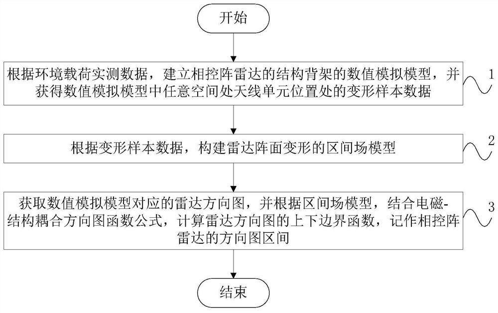
[0038] like figure 1 As shown, the present embodiment provides a method for analyzing the pattern interval of a phased array radar under uncertainty deformation, the method comprising:

[0039] Step 1: Accordin...


PUM


Abstract

The invention discloses a directional diagram interval analysis method under the uncertainty deformation of a phased array radar, and the method employs an interval measurement model to measure the uncertainty deformation of a radar array plane, and further quantifies the fluctuation law of the sidelobe of a phased array radar directional diagram under the uncertainty deformation. The method comprises the steps of analyzing an interval median, an interval radius and spatial correlation function construction of radar array plane uncertain deformation; measuring uncertain deformation of the radar array plane generated under the action of the service load by using an interval field measurement model; and introducing the interval field model of the radar array plane uncertainty deformation into an electromagnetic-structure coupling directional diagram function formula, calculating to obtain a directional diagram of the phased array radar, and further obtaining upper and lower boundaries of a sidelobe of the directional diagram of the phased array radar under the array plane uncertainty deformation. According to the technical scheme, the upper and lower boundary representation forms of the side lobes of the radar directional diagram are obtained, the influence rule of radar array plane uncertainty deformation on the radar directional diagram can be quantified, and guidance and reference are provided for radar actual engineering design and optimization.

Description

technical field [0001] The present application relates to the technical field of phased array radar, in particular, to a pattern interval analysis method under uncertainty deformation of phased array radar. Background technique [0002] Phased array radar is widely used in important fields such as long-range early warning, high maneuvering target detection and tracking, etc. It is a complex electromechanical thermal coupling multidisciplinary system. The flatness of the phased array radar front largely determines the precision and accuracy of target detection. Due to the influence of many uncertain factors such as wind load, ice and snow load, and solar radiation during service, the flatness of the phased array radar array will change, which will cause fluctuations or even deterioration of the radar pattern sidelobe pattern index, making the There is a large deviation in the detection of the target. [0003] In order to quantify the influence of the uncertain deformation o...

Claims


Application Information

Patent Timeline
Patent Type & Authority Applications(China)
IPC IPC(8): G06F30/23G06F111/10
CPCG06F30/23G06F2111/10Y02A90/10
Inventor 姜潮王中华倪冰雨李育
Owner HUNAN UNIV
Why Eureka
Try Eureka