

Electrochemical device and electronic device
A technology of electrochemical and conductive parts, applied in the direction of circuits, electrical components, battery pack components, etc., can solve the problem of many solder joints, achieve the effect of reducing solder joints, simplifying the process, and reducing the risk of puncture
- Summary
- Abstract
- Description
- Claims
- Application Information
AI Technical Summary
Problems solved by technology
Method used
Image

Examples
no. 1 example
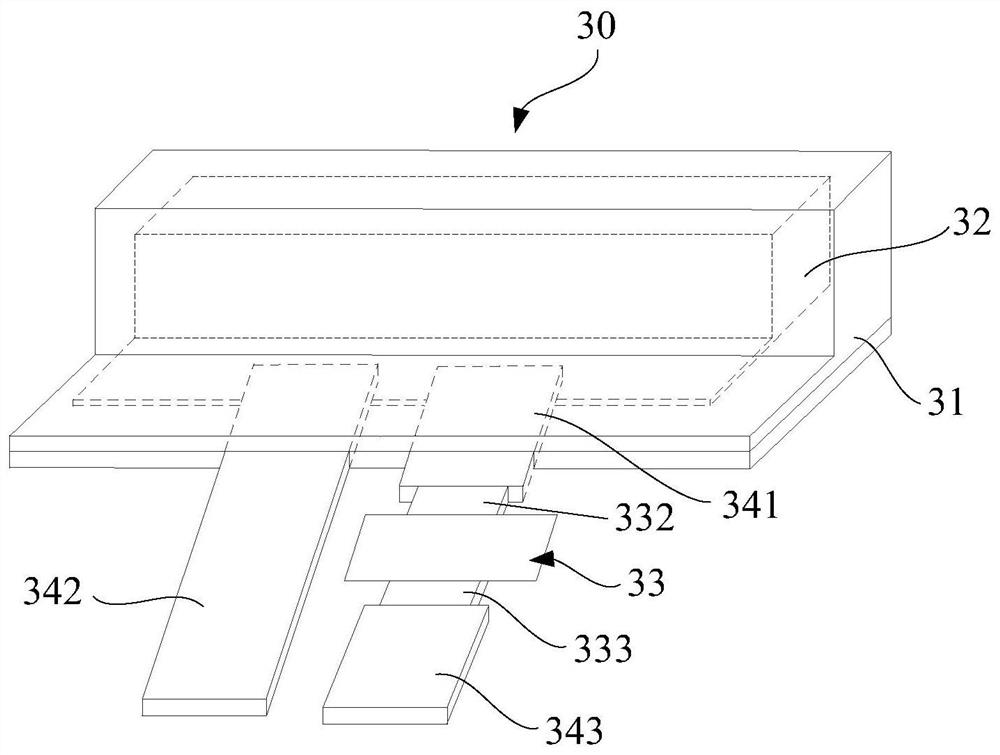
[0041] Please also refer to Figure 1 to Figure 5 As shown, the electrochemical device 30 includes a first casing 31 , an electrode assembly 32 , a protector 33 , a first tab 341 and a second tab 342 .
[0042] The electrode assembly 32 is located inside the first case 31 . The electrode assembly 32 can be formed by winding or stacking several pole pieces. These pole pieces are arranged in layers. One end of the first tab 341 and the second tab 342 extend into the first shell 31 and are aligned with the corresponding polarity. The other ends of the first tab 341 and the second tab 342 protrude from one side of the first housing 31 respectively.
[0043] According to the design that the electrochemical device 30 has positive and negative polarities, the pole piece of the electrode assembly 32 includes a positive pole piece and a negative pole piece and a separator arranged between the positive pole piece and the negative pole piece. Adaptively, the first tab 341 and the second...
no. 2 example
[0063] To facilitate description and distinguish differences between various embodiments, structural elements with the same name are identified with the same reference numerals herein. On the basis of the description of the first embodiment, but different from it, please also refer to Figure 8 , Figure 9 , Figure 10 , Figure 11 with Figure 12 In this embodiment, the electrochemical device 30 is not provided with the first tab 341 , and the first conductive member 332 of the protector 33 extends into the first housing 31 and is electrically connected to the electrode assembly 32 . It can be seen that this embodiment integrates the first conductive member 332 and the first tab 341 of the first embodiment, and the first conductive member 332 of this embodiment is not only the first conductive member 332 of the protector 33, but also Used as the first tab 341 .
[0064] In one implementation, if the direction in which the first conductive member 332 extends from the outs...
no. 3 example
[0072] On the basis of the description of the first embodiment, but different from it, please also refer to Figure 13 with Figure 14 , in this embodiment, the direction in which the first conductive member 332 protrudes from the second housing 331 is the same as the direction in which the second conductive member 333 protrudes from the second housing 331 . It should be understood that in Figure 13 In the state shown, the first conductive member 332 protrudes from the second housing 331 along the negative direction of the z-axis, and the second conductive member 333 protrudes from the second housing 331 along the negative direction of the z-axis and then faces the second shell The body 331 is turned over at a certain angle, and the third conductive member 343 is welded to the second conductive member 333 and followed by the second conductive member 333 to be turned over synchronously.
[0073] Such as Figure 14 As shown, when the electrode assembly 32 is not overheated, ...
PUM
 Abstract
Description
Claims
Application Information