
Liquid receiver

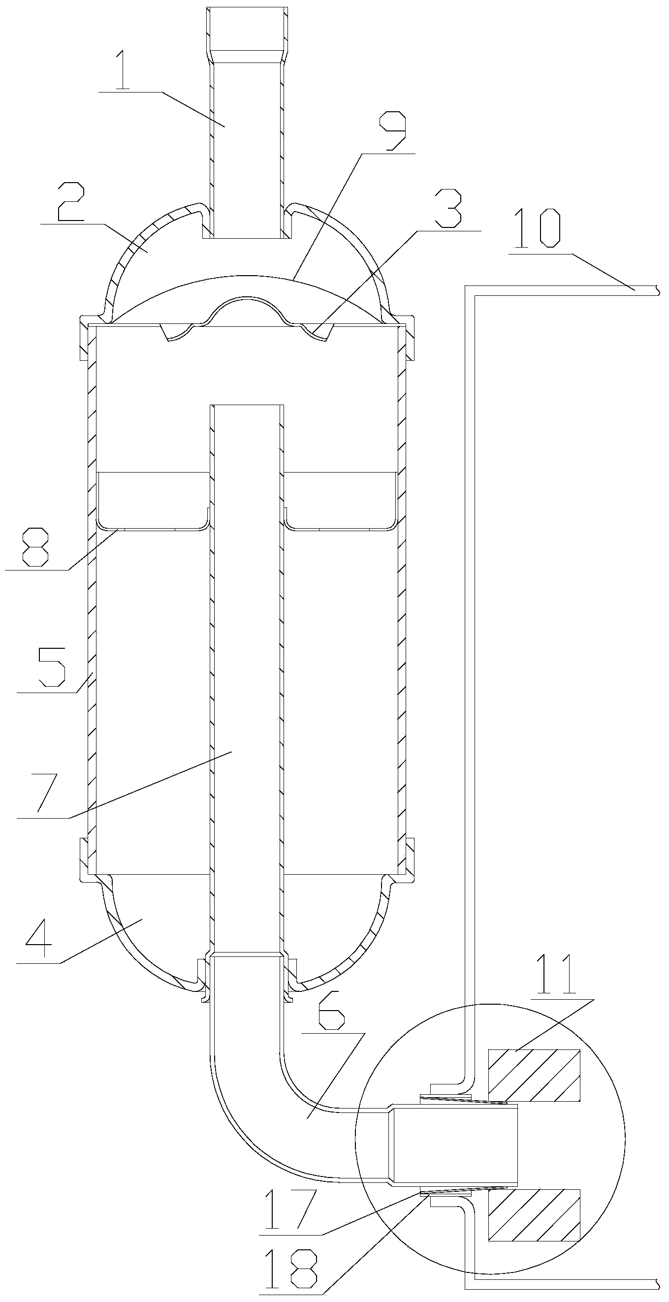
A liquid reservoir and cylinder technology, applied in the field of liquid reservoirs, can solve the problems of high welding cost and raw material cost, unstable welding quality of the liquid reservoir, and increased cost of the manufacturer, so as to achieve improved welding efficiency, simple structure, The effect of reducing the cost of raw materials

Active Publication Date: 2014-06-11
绍兴科辉电器有限公司
View PDF8 Cites 5 Cited by
  • Summary
  • Abstract
  • Description
  • Claims
  • Application Information

AI Technical Summary

Problems solved by technology

[0002] In the prior art, liquid reservoirs (such as figure 1 and figure 2 Shown) including air intake pipe, upper end cover, mesh seat, lower end cover, middle cylinder, air outlet pipe, iron pipe, bracket, filter screen; air inlet pipe and upper end cover are flame brazed; air outlet pipe and iron pipe are flame brazed The iron pipe and the lower end cover are brazed in the furnace; the middle cylinder body, the upper end cover and the lower end cover are brazed in the furnace; the bracket and the iron pipe are brazed in the furnace; It can be seen from the technical scheme that the existing liquid reservoir has problems such as many places that need to be welded and complex structure, so that the liquid reservoir has problems such as unstable welding quality, low welding efficiency, high welding cost and raw material cost.
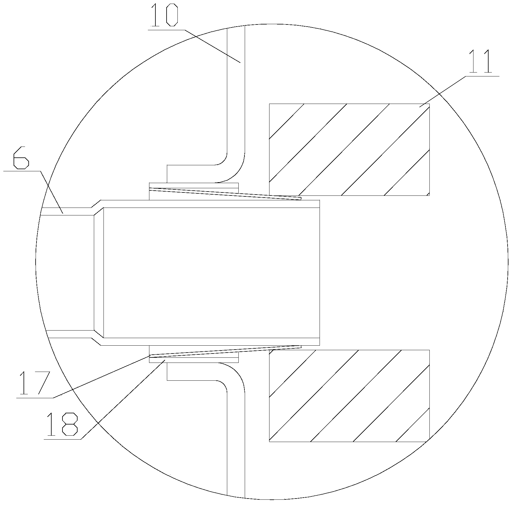
[0003] Moreover, when the existing liquid receiver is welded to the shell of the compressor, it is necessary to first press the connecting pipe of the cylinder into the cylinder hole for transitional connection. Put the copper pipe on the upper shell, and finally put the air outlet pipe into the cylinder connecting pipe. At this time, from the outside to the inside, the compressor shell shell, shell copper pipe, cylinder hole, cylinder connecting pipe and air outlet pipe are arranged, and the compressor shell shell , shell copper pipe, cylinder connecting pipe and gas outlet pipe are flame brazed at the same time, so that the liquid receiver and the compressor are connected as a whole; since all the connecting parts are welded by open flame brazing, the liquid receiver is welded during the welding process. If the heating time is long, a large amount of scale will be produced in the air outlet pipe of the liquid receiver and in the middle cylinder, and the impurities will also increase, which will easily lead to pipeline blockage; moreover, the existing liquid receiver uses more copper pipes, which increases the production cost of the manufacturer. cost

Method used


Image

  • Liquid receiver
  • Liquid receiver
  • Liquid receiver

Examples


Embodiment

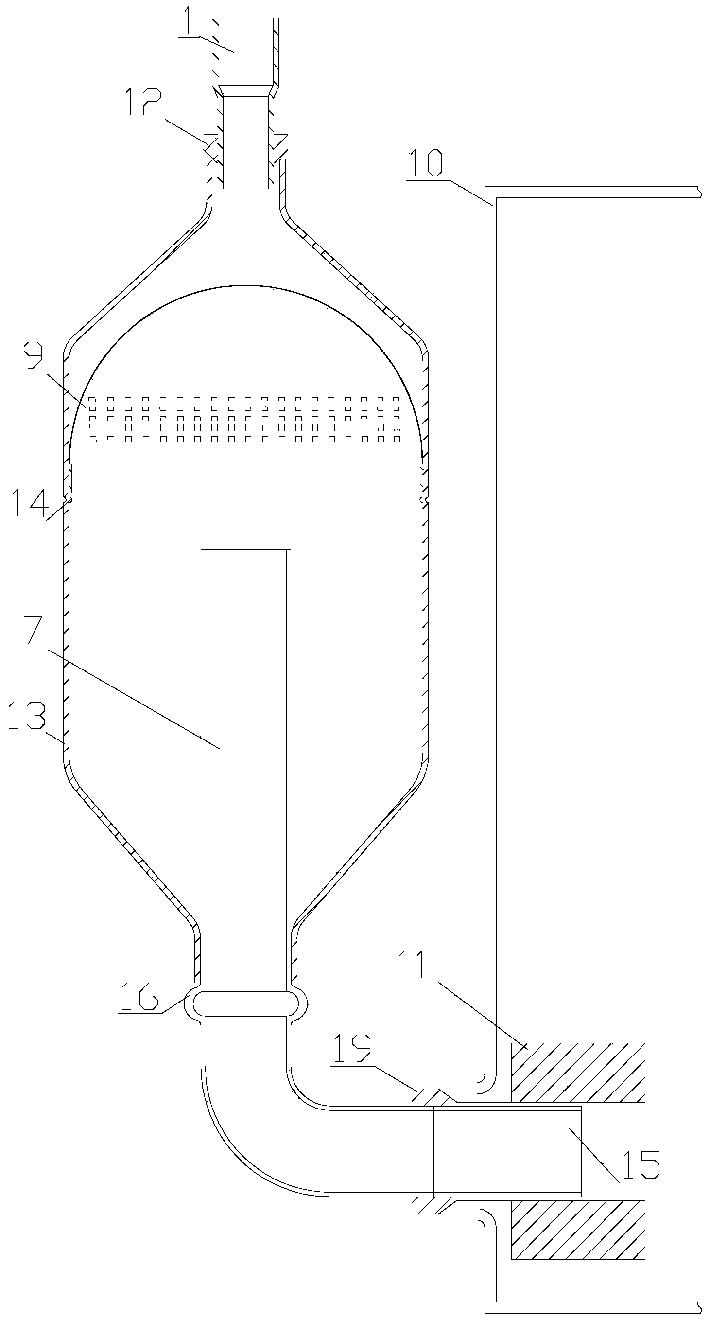
[0016] Embodiment: a kind of accumulator, is connected on the compressor, as image 3 As shown, the liquid reservoir includes a cylinder, the front end of the cylinder is provided with an air intake pipe, and the first flange is provided on the air intake pipe; the rear end of the cylinder is provided with an iron pipe, and the tail end of the iron pipe is provided with a centerless mill. Iron pipe, the connection between the iron pipe and the centerless grinding iron pipe is sleeved with a second flange, and the second flange is connected to the shell of the compressor; the centerless grinding iron pipe is connected to the compressor through interference fit The cylinder bore is connected; the flange, cylinder body and iron pipe are made of iron material, and the intake pipe is made of copper material; the cylinder body is also provided with a filter screen and positioning bumps, and the positioning bumps are rolled The process fixes the filter screen on the cylinder; the iro...


PUM


Abstract

The invention provides a liquid receiver. The liquid receiver is connected with a compressor and comprises a cylinder body, wherein an intake tube is arranged at the front end of the cylinder body and is provided with a first flange; an iron tube is arranged at the back end of the cylinder body, a centerless grinding iron tube is arranged at the tail end of the iron tube, and a second flange is sleeved outside a connection part of the iron tube and the centerless grinding iron tube and is connected with a compressor shell cylinder body; the centerless grinding iron tube is connected with an air cylinder hole of the compressor through interference fit; the flanges, the cylinder body and the iron tubes are made of an iron material, and the intake tube is made of a copper material; a filter screen and locating bumps are also arranged in the cylinder body, and the locating bumps fix the filter screen on the cylinder body by utilizing a rolling process; the iron tube is provided with locating points for helping the iron tube and the cylinder body to be located in a welding process.

Description

technical field [0001] The invention belongs to the technical field of refrigeration accessories, and in particular relates to a liquid receiver. Background technique [0002] In the prior art, liquid reservoirs (such as figure 1 and figure 2 Shown) including air intake pipe, upper end cover, mesh seat, lower end cover, middle cylinder, air outlet pipe, iron pipe, bracket, filter screen; air inlet pipe and upper end cover are flame brazed; air outlet pipe and iron pipe are flame brazed The iron pipe and the lower end cover are brazed in the furnace; the middle cylinder body, the upper end cover and the lower end cover are brazed in the furnace; the bracket and the iron pipe are brazed in the furnace; It can be seen from the technical scheme that the existing liquid reservoir has problems such as many places to be welded and complex structure, which lead to problems such as unstable welding quality, low welding efficiency, high welding cost and raw material cost in the liq...

Claims


Application Information

Patent Timeline
IPC IPC(8): F25B43/00
Inventor 王志祥
Owner 绍兴科辉电器有限公司
Learn More