Pulse width modulation type power converter

A technology of pulse width modulation and power converter, which is applied in the direction of adjusting electric variables and output power conversion devices, instruments, etc. It can solve the problems of large output voltage, ripple, long circuit response time, etc., and achieve the effect of stabilizing the output voltage

Active Publication Date: 2021-06-15
UNIV OF ELECTRONICS SCI & TECH OF CHINA
View PDF10 Cites 3 Cited by
  • Summary
  • Abstract
  • Description
  • Claims
  • Application Information

AI Technical Summary

Problems solved by technology

When the load change causes the output voltage to change, wait until V P The next rising edge or falling edge comes, the oscillator will change the oscillation time to adjust the output voltage, due to V P The cycle is larger, and the circuit response time will be longer, so a relatively large output voltage ripple will be generated.

Method used


Image

  • Pulse width modulation type power converter
  • Pulse width modulation type power converter
  • Pulse width modulation type power converter

Examples


Embodiment

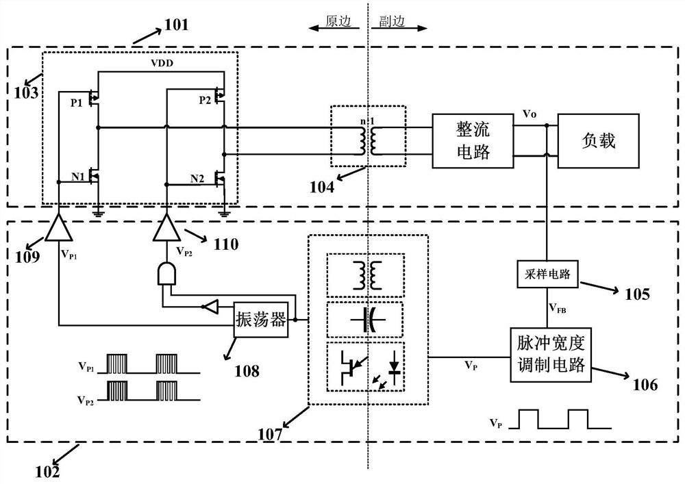
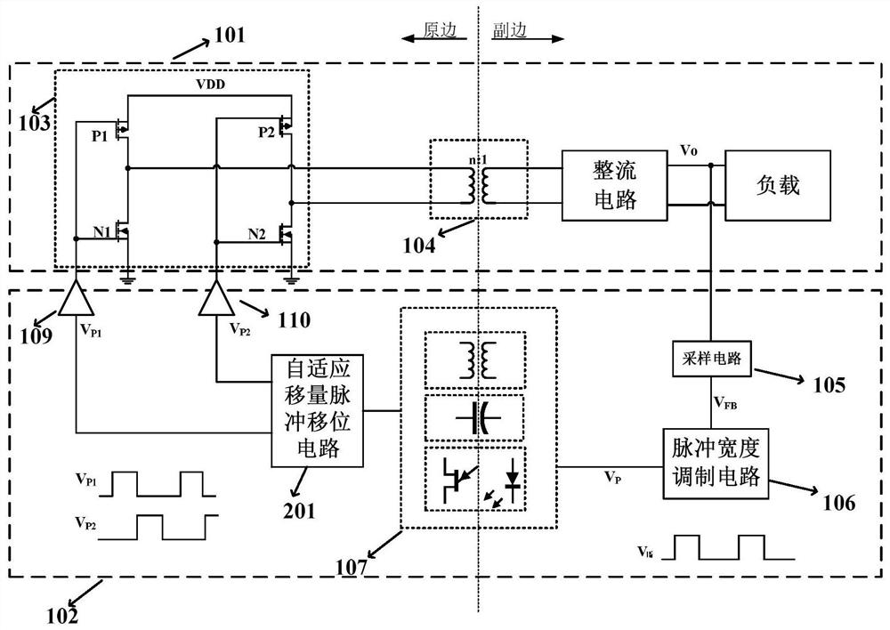
[0026] like Figure 4 As shown, it is a system structure diagram of the pulse width modulation power converter of the embodiment; it includes a conversion circuit 101 and a feedback control circuit 102;

[0027] The conversion circuit 101 includes a full-bridge inverter circuit 103, a transformer 104, a rectifier circuit and a load;

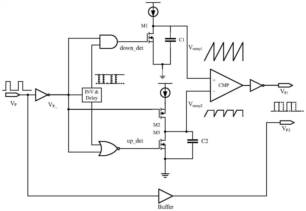
[0028] The feedback control circuit 102 includes a sampling circuit 105, a pulse width modulation circuit 401, a signal isolation transmission channel 107, an adaptive displacement pulse shift circuit 201, a first drive circuit 109 and a second drive circuit 110;

[0029] The drains of the first PMOS transistor P1 and the first NMOS transistor N1 in the full-bridge inverter circuit are connected to one end of the primary side of the transformer 104, and the drains of the second PMOS transistor P2 and the second NMOS transistor N2 are connected to the primary side of the transformer 104. The other end of the side is connected; the two ends of the...


PUM


Abstract

The invention discloses a pulse width modulation type power converter, and belongs to the technical field of integrated circuits. The power converter comprises a conversion circuit and a feedback control circuit. The conversion circuit comprises a full-bridge inverter circuit, a transformer, a rectification circuit and a load; the feedback control circuit comprises a sampling circuit, a pulse width modulation circuit, a signal isolation transmission channel, a self-adaptive shift pulse shift circuit, a first driving circuit and a second driving circuit. According to the pulse width modulation type power converter provided by the invention, two signals for controlling the full-bridge inverter circuit are non-complementary pulse signals, the feedback control circuit can adjust the pulse width of feedback signals according to the change of a sampling voltage so as to stabilize an output voltage; and each pulse for controlling the full-bridge inverter circuit contains control information, therefore, the energy transmitted to the load can be rapidly adjusted according to the change of the load, the output voltage is stabilized, and the good transient response speed enables the output voltage to have small voltage ripples.

Description

technical field [0001] The invention belongs to the technical field of integrated circuits, and relates to a direct current to direct current power converter, in particular to a pulse width modulation power converter. Background technique [0002] Isolated power supplies are widely used in medical equipment, communication networks, electric vehicles, and robots to protect the safety of users and equipment. The full-bridge inverter circuit is a common structure in the topology of isolated power supplies. In practical applications, in order to ensure that the power system can have a stable output under different loads or unstable input voltages, the general isolated power system also needs an isolated feedback control loop. [0003] The full-bridge inverter circuit is generally a "bridge" structure composed of four MOS tubes, including two PMOSs connected to the positive pole of the power supply and two NMOSs connected to the negative pole of the power supply, and the drain of...

Claims


Application Information

Patent Timeline
Patent Type & Authority Applications(China)
IPC IPC(8): H02M3/335H02M7/5387H02M7/5395H02M1/088H02M1/092H02M1/14
CPCH02M3/3353H02M7/53871H02M7/5395H02M1/088H02M1/092H02M1/14
Inventor 伍荣翔雷伍峰
Owner UNIV OF ELECTRONICS SCI & TECH OF CHINA
Why Eureka
Try Eureka