Novel professional light guide plate CCD film laminating machine

A light guide plate and film laminating machine technology, which is applied in chemical instruments and methods, cleaning methods and utensils, cleaning methods using gas flow, etc., can solve the problems of unstable production of light guide plate film, unstable cutting effect of light guide plate, surface Instable film cutting and other problems, to achieve the effect of reducing floating around, stable adhesion removal effect, and stable cutting effect

Inactive Publication Date: 2021-06-18
DONGGUAN YUANLI ELECTRONICS TECH
View PDF8 Cites 2 Cited by
  • Summary
  • Abstract
  • Description
  • Claims
  • Application Information

AI Technical Summary

Problems solved by technology

In the production of the light guide plate, it is also necessary to cover the surface of the light guide plate with a surface film such as a reflective film or a light-enhancing film. The film of the light guide plate needs to use a laminating machine for the light guide plate. The surface film on the light plate is cut and separated for material collection. When the surface film is cut, the strip-shaped surface film is subjected to a transverse shear force, and the surface film is prone to offset, thereby causing the light guide plate to move, resulting in the cutting of the surface film. Unstable, which in turn makes the film production of the light guide plate unstable
[0003] In view of the above-mentioned related technologies, the inventor believes that there is a defect that the cutting effect of the surface film of the light guide plate is unstable during the film coating process of the light guide plate, which causes the production of the film coating of the light guide plate to be unstable.

Method used


Image

  • Novel professional light guide plate CCD film laminating machine
  • Novel professional light guide plate CCD film laminating machine
  • Novel professional light guide plate CCD film laminating machine

Examples


Embodiment 1

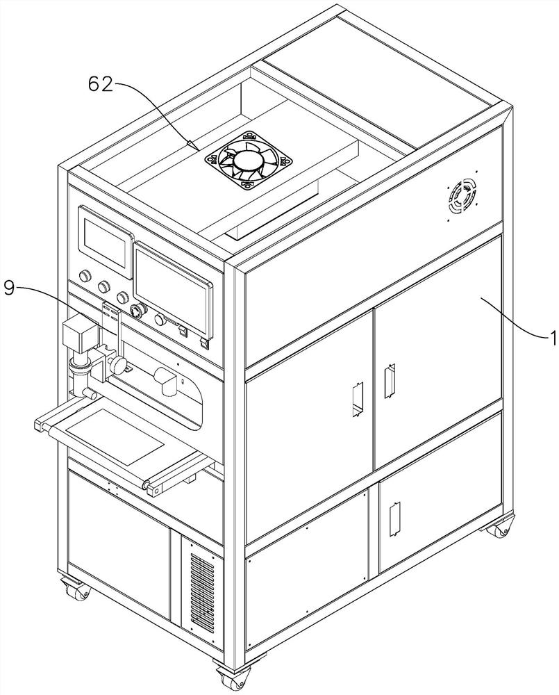
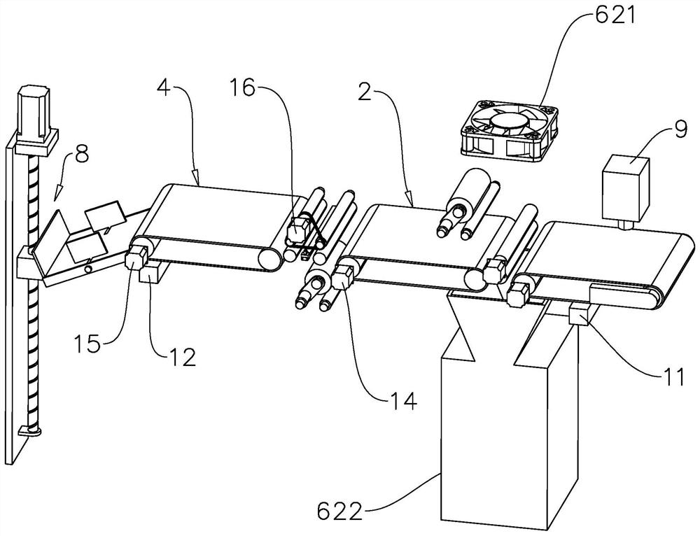
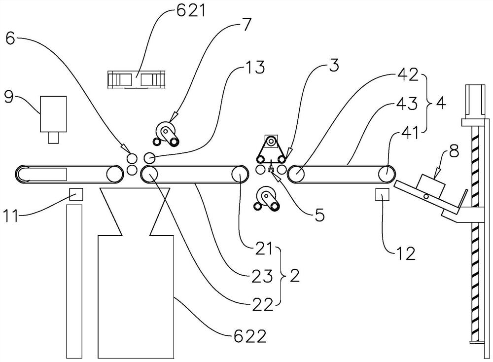
[0044] A new type of professional light guide plate CCD laminating machine, refer to figure 1 and figure 2 , comprising a frame 1, one end of the frame 1 along its own length direction is the feed end and the other end is the discharge end, the feed end of the frame 1 is provided with a first transmission mechanism 2, and the discharge end of the frame 1 is provided with There is a second conveying mechanism 4, and the first conveying mechanism 2 and the second conveying mechanism 4 are located on the same level. combine image 3 The first transmission mechanism 2 includes a first driving roller 21, a first driving roller 22, and a first conveyor belt 23 covering the first driving roller 21 and the first driving roller 22, and the two ends of the first driving roller 21 are rotatably connected to Frame 1, the first drive roller 22 is also rotatably connected to the frame 1, and the frame 1 is provided with a first motor 14 at one end position of the first drive roller 21, a...

Embodiment 2

[0055] The difference between the embodiment and the embodiment is that, with reference to Figure 9 and Figure 10 One groove wall of the slot 521 is provided with a mounting groove 523 and the opposite groove wall is provided with a locking groove 524. The notches are set relative to each other. A locking component 54 is installed in the installation groove 523 . The locking component 54 includes a compression spring 541 and a locking block 542 . The knife handle is provided with a lock hole 531, and the lock hole 531 is connected to the installation groove 523 and the lock groove 524 at the same time. The cutting blade 53 is locked and fixed in the slot 521 . In this embodiment, preferably, the lock block 542 is spherical, and the aperture of the lock hole 531 is slightly smaller than the diameter of the lock block 542. When taking out the cutting blade 53, only a large pulling force is required, and the lock block 542 can be locked in the lock hole 531. The pressure of...


PUM


Abstract

The invention relates to a novel professional light guide plate CCD film laminating machine. The novel professional light guide plate CCD film laminating machine comprises a machine frame, a first conveying mechanism, a transition mechanism, a second conveying mechanism and a cutting mechanism, the first conveying mechanism, the transition mechanism and the second conveying mechanism are sequentially arranged on the machine frame in the conveying direction of a light guide plate, and the transition mechanism comprises two clamping and pressing conveying assemblies. The cutting mechanism is arranged between the two clamping and conveying assemblies, each clamping and conveying assembly comprises an upper roller and a lower roller, and the upper rollers and the lower rollers clamp and convey the light guide plate. A first electrostatic rod and a dust removal mechanism are arranged at the feeding end of the machine frame, a second electrostatic rod and a material collecting mechanism are arranged at the discharging end of the machine frame, one installation mechanism is arranged at the position, close to the feeding end, of the machine frame, the other installation mechanism is also arranged at the position, close to the discharging end, of the machine frame, and the two installation mechanisms are used for installing a reflecting film and a bright enhancement film correspondingly. A pressing roller is arranged at the position, close to the first conveying mechanism, of the machine frame. The novel professional light guide plate CCD film laminating machine has the effect of improving the film laminating production stability of the light guide plate.

Description

technical field [0001] This application relates to the technical field of light guide plate production, in particular to a new type of professional light guide plate CCD laminating machine. Background technique [0002] The light guide plate is made of optical-grade acrylic / PC plate, and then high-tech materials with extremely high refractive index and non-absorbing light are used to engrave the bottom surface of the optical-grade acrylic plate with laser engraving, V-shaped cross grid engraving, UV screen printing technology prints light guide points. In the production of the light guide plate, it is also necessary to cover the surface of the light guide plate with a surface film such as a reflective film or a light-enhancing film. The film of the light guide plate needs to use a laminating machine for the light guide plate. The surface film on the light plate is cut and separated for material collection. When the surface film is cut, the strip-shaped surface film is subje...

Claims


Application Information

Patent Timeline
Patent Type & Authority Applications(China)
IPC IPC(8): B08B5/02B08B7/00B08B13/00B29C63/02B29C63/00
CPCB08B5/023B08B7/0028B08B13/00B29C63/02B29C63/0004
Inventor 阮绪红徐大良陈媛媛
Owner DONGGUAN YUANLI ELECTRONICS TECH
Why Eureka
Try Eureka