Continuous die cutting device with good limiting effect for tank end cover and application method of continuous die cutting device
A technology of die-cutting and tank ends, which is applied in the field of mechanical processing, can solve the problems of increasing the proportion of leftover materials, increasing costs, and increasing the labor intensity of staff, and achieves the effects of precise and controllable spacing, reduced labor intensity, and reduced waste production
- Summary
- Abstract
- Description
- Claims
- Application Information
AI Technical Summary
Problems solved by technology
Method used
Image
Examples
Embodiment 1
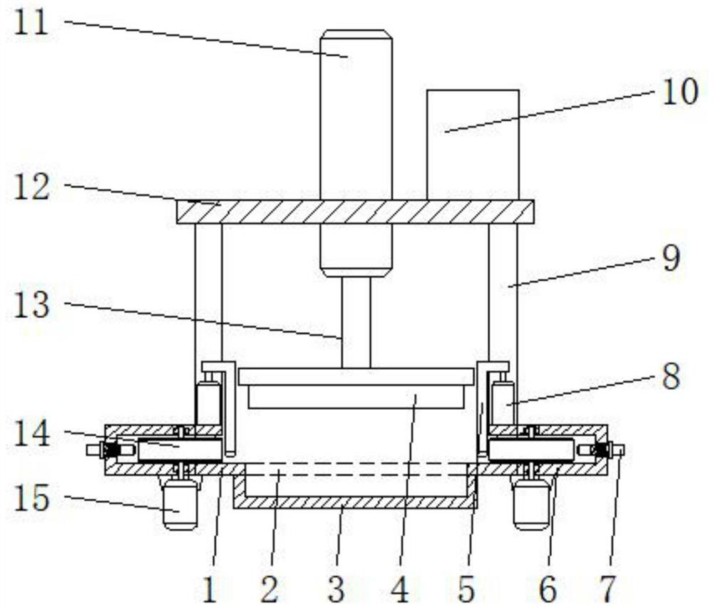
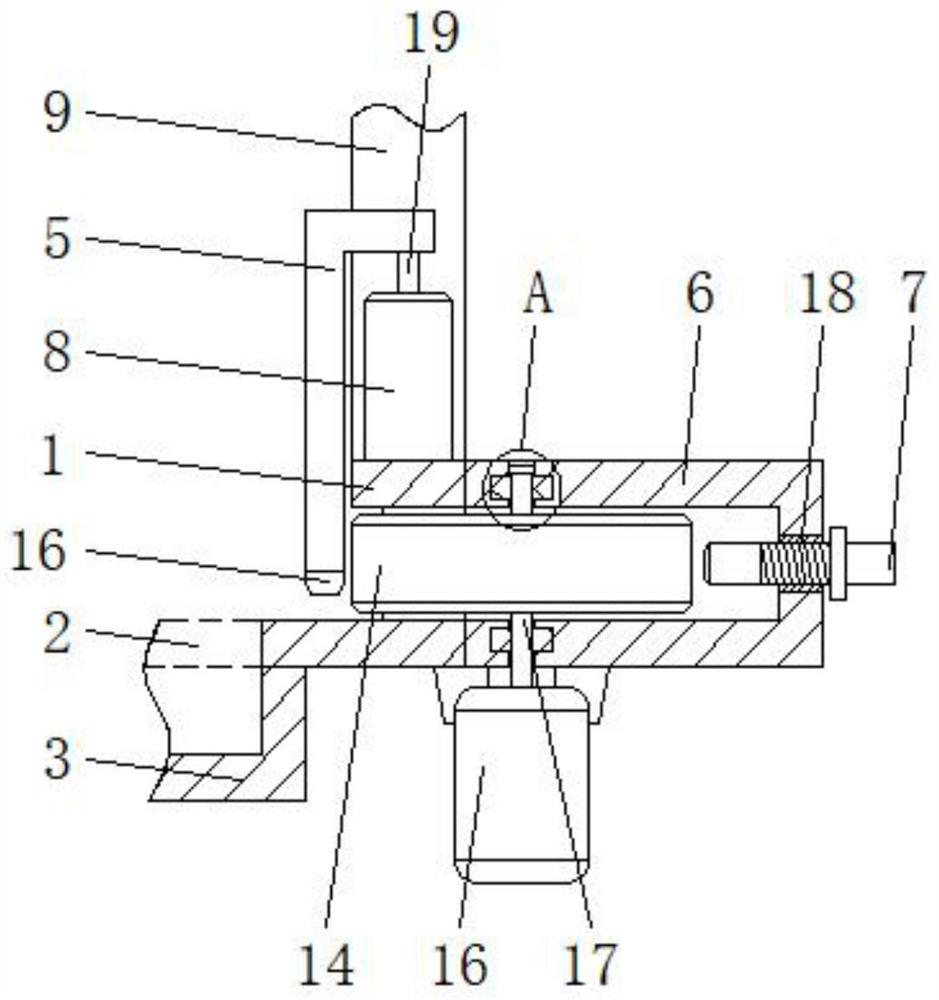
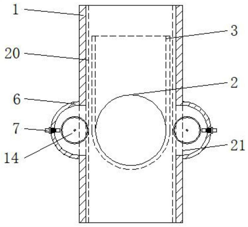
[0030] A continuous die-cutting device for tank end caps with a good position-limiting effect, comprising a feeding plate 1, a forming hole 2, a position-limiting plate 5, a driving chamber 6, a first hydraulic cylinder 8, a second hydraulic cylinder 11 and a fixing plate 12, The upper surface of the feeding plate 1 is provided with a fixed plate 12, and the outer walls of both sides of the feeding plate 1 are symmetrically provided with the driving chamber 6, and the inner walls of both sides of the feeding plate 1 are symmetrically provided with feeding grooves 20, and the inner wall of the bottom end of the feeding plate 1 is opened. There is a forming hole 2, the lower surface of the feeding plate 1 is welded with a discharge groove 3, the discharge groove 3 is located below the forming hole 2, and the inner wall diameter of the discharging groove 3 is larger than the inner wall diameter of the forming hole 2, and the second hydraulic cylinder 11 drives the second The hydra...
Embodiment 2
[0032] Servo motors 15 are installed on the lower surfaces of the two driving bins 6, and pulleys 14 are installed for rotation inside the driving bins 6, and through grooves 21 are provided on both sides of the feeding trough 20, and the through grooves 21 communicate with the inside of the driving bins 6, One side of the pulley 14 runs through the through groove 21 and is placed inside the feeding trough 20;
[0033] The inner walls of the upper and lower ends of the driving chamber 6 are provided with through holes 22, and the inside of the through holes 22 are embedded with bearings 24. The upper end of the servo motor 15 is provided with a rotating shaft 17 that runs through the bearing 24 and the inside of the pulley 14, and the upper end of the rotating shaft 17 is provided with a limit block. 23. The two driving chambers 6 are symmetrically provided with screw holes 18 at one end facing away from each other. Displacement sensors 7 are inserted and rotated inside the scr...
Embodiment 3
[0036]The surface of the fixed plate 12 is embedded with a second hydraulic cylinder 11, and a controller 10 is installed on one side of the upper surface of the fixed plate 12. The four corners of the lower surface of the fixed plate 12 are welded with supporting columns 9, and the lower ends of the supporting columns 9 are connected to the feeding plate. 1. The upper surface is welded, the second hydraulic cylinder 11 is movably plugged with the second hydraulic rod 13, and the lower end of the second hydraulic rod 13 is equipped with a die-cutting block 4, which is matched with the forming hole 2;
[0037] The first hydraulic cylinder 8 is symmetrically installed on both sides of the upper surface of the feeding plate 1, and the upper end of the first hydraulic cylinder 8 is movably connected with the first hydraulic rod 19. The upper end of the first hydraulic rod 19 is connected to the limit plate 5, and the two limit plates The plate 5 is symmetrically distributed inside ...
PUM
 Abstract
Description
Claims
Application Information
 - R&D
- Intellectual Property
- Life Sciences
- Materials
- Tech Scout
- Unparalleled Data Quality
- Higher Quality Content
- 60% Fewer Hallucinations
Browse by: Latest US Patents, China's latest patents, Technical Efficacy Thesaurus, Application Domain, Technology Topic, Popular Technical Reports.
© 2025 PatSnap. All rights reserved.Legal|Privacy policy|Modern Slavery Act Transparency Statement|Sitemap|About US| Contact US: help@patsnap.com


