IC packaged chip discharging device

A technology of discharging device and chip loading, applied in transportation and packaging, conveyor objects, stacking of objects, etc., can solve the problems of low production efficiency, low degree of automation, inability to automatically replace material tubes, etc., saving time , High degree of automation, the effect of reducing the frequency of manual replacement of the storage tube

Active Publication Date: 2021-06-18
四川明泰微电子科技股份有限公司
View PDF14 Cites 6 Cited by
  • Summary
  • Abstract
  • Description
  • Claims
  • Application Information

AI Technical Summary

Problems solved by technology

[0002] IC packaged chips need to be loaded into empty material tubes for storage after production testing and screening are completed. Although the existing equipment can automatically load IC packaged chips into empty material tubes, they cannot automatically replace the material tubes, and the material tubes are full of ICs. After the chip is packaged, it needs to be manually removed and then replaced with an empty material tube. The degree of automation is low and the production efficiency is not high.

Method used


Image

  • IC packaged chip discharging device
  • IC packaged chip discharging device
  • IC packaged chip discharging device

Examples


specific Embodiment approach

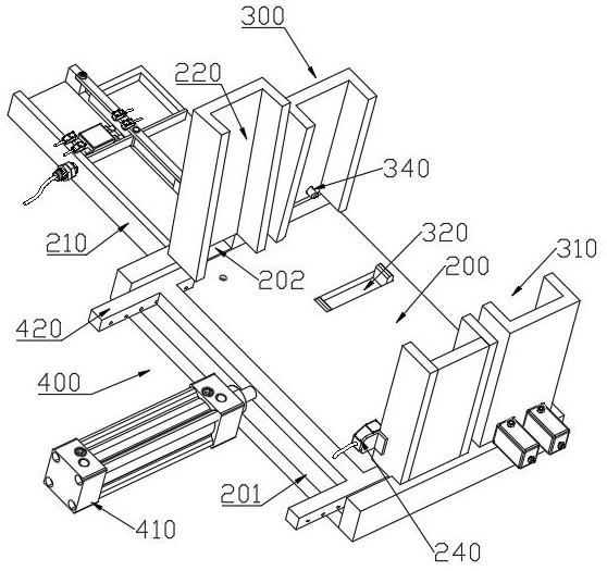
[0053] Specific implementation method: first stack a plurality of empty material storage tubes 100 in the material tube storage tank 220. At this time, the opening of the bottommost material storage tube 100 is directly connected with the feed port 202 through the guide sleeve 120. The push rod 400 in such figure 1 In the recovery state shown, a gap is reserved between the front end of the push rod 410 and the side wall of the storage tube 100 at the bottom to prevent the storage tube 100 from falling smoothly; then the IC package chip can be loaded until the IC package chip Loaded to the position of the through hole 101, because the IC packaged chip cuts off the sensing area of ​​the proximity switch 230, the proximity switch 230 will receive the in-position signal of the IC packaged chip, and the device judges that the IC packaged chip in the storage tube 100 has passed through the signal. When it is full, it will stop and continue to discharge; meanwhile, the push rod 400 s...


PUM


Abstract

According to an IC packaged chip discharging device, the section of a storage pipe is rectangular, one end of the storage pipe is provided with an opening, and a through hole is machined in the opening end; a bottom plate is provided with a pipe sliding groove and a feeding groove, the feeding groove communicates with the pipe sliding groove, the communication position is a feeding port of an IC packaged chip, a pipe storage groove is formed above the feeding port, the storage pipe is stacked in the pipe storage groove in a sliding mode, the opening of the storage pipe is aligned to the feeding port during discharging, the bottom plate is provided with a proximity switch corresponding to the through hole, and a gap is formed between the bottom face of the pipe storage groove and the bottom face of the pipe sliding groove; a pipe stacking mechanism comprises a pipe stacking groove and a lifting plate, and a gap is formed between the bottom face of the pipe stacking groove and the bottom face of the pipe sliding groove; the lifting plate penetrates through the bottom of the pipe sliding groove, and supporting rods are arranged on the two side walls of the pipe stacking groove; and a pushing rod is of an H-shaped structure, is connected to a pushing air cylinder and is provided with push rods parallel to each other, and the thickness of the push rods is smaller than that of the storage pipe. The device is high in automation degree and beneficial for improving production efficiency.

Description

technical field [0001] The invention belongs to the technical field of IC packaging chip production, in particular to an IC packaging chip discharging device. Background technique [0002] IC packaged chips need to be loaded into empty material tubes for storage after production testing and screening are completed. Although the existing equipment can automatically load IC packaged chips into empty material tubes, they cannot automatically replace the material tubes, and the material tubes are full of ICs. After the chip is packaged, it needs to be manually taken out and then replaced with an empty material tube. The degree of automation is low and the production efficiency is not high. Contents of the invention [0003] In order to solve the deficiencies of the existing technology, the present invention provides an IC packaging chip discharge device, which automatically pushes the storage tubes filled with IC packaging chips to the stacking tube groove for stacking and tem...

Claims


Application Information

Patent Timeline
Patent Type & Authority Applications(China)
IPC IPC(8): B65G47/82B65G57/20
CPCB65G47/82B65G57/20
Inventor 李蛇宏杨益东
Owner 四川明泰微电子科技股份有限公司
Why Eureka
Try Eureka