
Optical fiber preform core layer sintering equipment laser bracket reforming structure

An optical fiber preform and sintering equipment technology, applied in glass manufacturing equipment, manufacturing tools, glass production and other directions, can solve the problems of loose body positioning, the loose body cannot be completely transparent, and the laser bracket is shaking, and the effect of reducing product scrap is achieved.

Active Publication Date: 2021-06-18
TONGDING INTERCONNECTION INFORMATION CO LTD
View PDF6 Cites 2 Cited by
  • Summary
  • Abstract
  • Description
  • Claims
  • Application Information

AI Technical Summary

Problems solved by technology

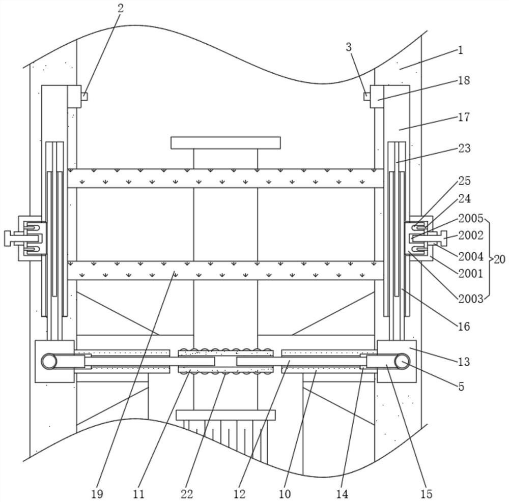
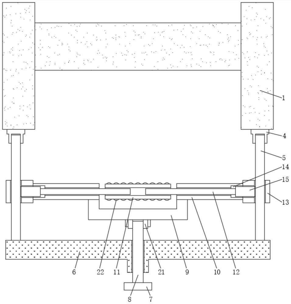
[0004] The invention provides a modified structure of the laser support for the sintering equipment of the core layer of the optical fiber prefabricated rod, which has the advantage of reducing product scrapping, so as to solve the problem in the prior art that the current laser support is installed on the platform, and the laser support will be caused when the production personnel walk back and forth. Shaking, not accurately positioning the bottom tip of the loose body, which eventually leads to the inability of the sintered loose body to be completely transparent, resulting in product waste

Method used


Image

  • Optical fiber preform core layer sintering equipment laser bracket reforming structure
  • Optical fiber preform core layer sintering equipment laser bracket reforming structure
  • Optical fiber preform core layer sintering equipment laser bracket reforming structure

Examples


Embodiment Construction

[0021] The following will clearly and completely describe the technical solutions in the embodiments of the present invention with reference to the accompanying drawings in the embodiments of the present invention. Obviously, the described embodiments are only some, not all, embodiments of the present invention. Based on the embodiments of the present invention, all other embodiments obtained by persons of ordinary skill in the art without making creative efforts belong to the protection scope of the present invention.

[0022] see Figure 1-5 , the present invention discloses a fiber preform core layer sintering equipment laser bracket transformation structure, including a tower 1, a transmitting end 2 and a receiving end 3, the front of the tower 1 is fixedly connected with a fixing part 4, which can be mounted on the tower 1 Open the threaded hole, and fix the fixing part 4 at the position of the threaded hole through the hexagon socket head cap screw to realize the install...


PUM


Abstract

The invention discloses an optical fiber preform core layer sintering equipment laser bracket reforming structure, and relates to the technical field of optical fiber preform manufacturing devices. The optical fiber preform core layer sintering equipment laser bracket reforming structure comprises a tower frame, a transmitting end and a receiving end, wherein the front face of the tower frame is fixedly connected with a fixing piece, the inner wall of the fixing piece is fixedly connected with the surfaces of round rods, the number of the round rods is two, the ends, away from the tower frame, of the two round rods are fixedly connected with the back face of a transverse rod, a driving plate is arranged on the front face of the transverse rod, and an adjusting screw rod is fixedly connected with the back face of the driving plate. By arranging the fixing piece, the round rods, the bushing, the cylinder and the mounting plate, the problems that in the prior art, when a laser bracket is mounted on a platform at present, when production personnel walk back and forth, the laser bracket shakes, the tip of the bottom of a loose body is not accurately positioned, and finally the sintered loose body cannot be completely transparent, and product waste is caused are solved.

Description

technical field [0001] The invention relates to the technical field of optical fiber prefabricated rod manufacturing devices, in particular to a laser bracket reconstruction structure for an optical fiber preformed rod core layer sintering equipment. Background technique [0002] The optical fiber preform is the key raw material in the optical fiber drawing process. It consists of a core rod and an outer cladding. At present, the core rod made of an optical fiber preform is produced by a vapor phase axial deposition process, and the vapor phase axial deposition process includes deposition equipment. The opaque silicon dioxide loose body is produced, and then sintered at high temperature by the sintering equipment to obtain a transparent core rod for subsequent stretching and external vapor deposition process. When the optical fiber preform is produced, the product produced by the deposition equipment It is an opaque silicon dioxide loose body, which needs to enter the sinter...

Claims


Application Information

Patent Timeline
IPC IPC(8): C03B37/018
CPCC03B37/01853Y02P40/57
Inventor 沈小平谷东东朱陈明陈尚加王祥王樯
Owner TONGDING INTERCONNECTION INFORMATION CO LTD
Learn More