Pipeline conveyor capable of achieving pipeline replacement conveniently and for hydrogen refueling station

A technology for pipeline transportation and hydrogen refueling stations, applied in pipeline heating/cooling, pipeline systems, pipes/pipe joints/fittings, etc., can solve problems such as temperature reaching, liquid gas spontaneous combustion, liquid hydrogen heating, etc., to prevent heat from spontaneous combustion, Reduce the generation of static electricity and facilitate disassembly and assembly

Active Publication Date: 2021-06-18
河南氢枫能源技术有限公司 +1
View PDF5 Cites 0 Cited by
  • Summary
  • Abstract
  • Description
  • Claims
  • Application Information

AI Technical Summary

Problems solved by technology

[0005] The purpose of the present invention is to provide a pipeline conveyor for hydrogen refueling stations that is convenient for pipeline replacement, so as to solve the problem that the liquid hydrogen inside the existing pipeline conveyor proposed in the above background technology flows and collides for a long time, which easily leads to the heating of liquid hydrogen , which will easily cause the temperature inside the equipment to reach the ignition point of hydrogen, which will easily lead to the problem of spontaneous combustion of liquid gas

Method used


Image

  • Pipeline conveyor capable of achieving pipeline replacement conveniently and for hydrogen refueling station
  • Pipeline conveyor capable of achieving pipeline replacement conveniently and for hydrogen refueling station
  • Pipeline conveyor capable of achieving pipeline replacement conveniently and for hydrogen refueling station

Examples


Embodiment Construction

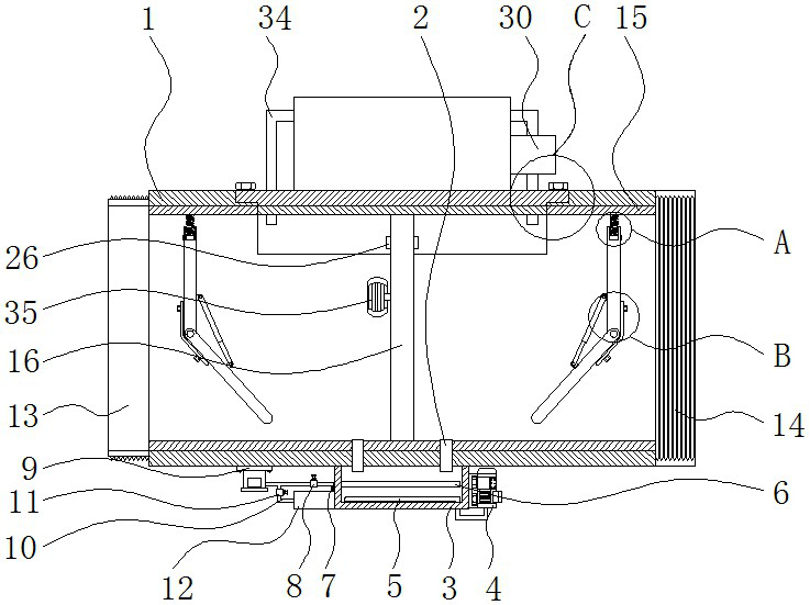
[0060] See Figure 1-5 The present invention provides a technical solution: a pipe conveyor for a hydrogen station for pipe replacement, including:

[0061] The pipe body 1, the left side of the conduit body 1 fixes the threaded joint 13, and the right side of the pipe body 1 has a threaded joint 14;

[0062]The first connecting conduit 2 is formed through the lower wall of the conduit body 1, and the first connecting conduit 2 is provided with a central axis symmetry of the conduit body 1;

[0063] Cooling the casing 3, which is fixed to the lower end of the pipe body 1;

[0064] The condenser 4 is mounted on the right side of the cooling casing 3;

[0065] The condenser 5 is attached to the lower end of the condenser 4, and the liquid hydrogen inside the apparatus can be delivered to the cooling casing 3 through the first connecting conduit 2, and the liquid hydrogen inside the pipe body 1 is passed through the condenser 4 and the condenser 5. The cooling treatment can prevent th...


PUM


Abstract

The invention relates to a pipeline conveyor capable of achieving pipeline replacement conveniently and for a hydrogen refueling station. The pipeline conveyor comprises a pipeline body and first connecting guide pipes. A threaded connector is fixed on the left side of the pipeline body, and a threaded connecting sleeve is welded on the right side of the pipeline body. The first connecting guide pipes penetrate through the lower wall of the pipeline body, and the two first connecting guide pipes are symmetrically arranged about the central axis of the pipeline body. The pipeline conveyor capable of achieving pipeline replacement conveniently and for the hydrogen refueling station has the beneficial effects that the pipeline conveyor has the cooling and deoxidizing functions, and therefore the spontaneous combustion condition of liquid hydrogen in the pipeline conveyor can be reduced, meanwhile, the pipeline conveyor can also absorb charges generated by collision, and electric sparks are avoided; and other mechanisms in the pipeline conveyor can be independently disassembled and assembled, pipelines of the pipeline conveyor can be replaced, meanwhile, after the temperature in the pipeline conveyor reaches a certain value, the pipeline conveyor can be blocked, heat is prevented from being transmitted to other places, and therefore liquid hydrogen in the whole set of pipeline conveyor is prevented from being heated and spontaneously combusted, and losses are reduced.

Description

Technical field [0001] The present invention relates to the technical field of transportation techniques of hydrogenation station, and is specifically a hydrogen stop pipe conveyor for facilitating pipe replacement. Background technique [0002] The hydrogen station is a gas station that supplies hydrogen gas to the fuel cell vehicle, and the hydrogen transport machine is required to be transported using a pipe conveyor to facilitate processing and use of other equipment in the hydrogenation station. [0003] The liquid hydrogen inside the existing pipe conveyor flows for a long time, which is likely to cause liquid hydrogen to heat, thereby easily causing the temperature inside the device to reach the combustion point of hydrogen, which is likely to cause liquid gas to generate spontaneous combustion. [0004] Therefore, a hydrogen stop pipe conveyor for facilitating hydrogen replacement is required for the above problem. Inventive content [0005] It is an object of the presen...

Claims


Application Information

Patent Timeline
Patent Type & Authority Applications(China)
IPC IPC(8): F16L53/70F16L55/10F17D1/02
CPCF16L55/10F17D1/02F16L53/70Y02E60/34Y02P90/45
Inventor 方沛军宣锋姜方伍远安曹俊
Owner 河南氢枫能源技术有限公司
Why Eureka
Try Eureka