Multifunctional dehumidifier

A dehumidifier, multi-functional technology, applied in mechanical equipment, electromechanical devices, heating methods, etc., can solve problems such as the existence of more bacteria, achieve the effect of increasing speed and angle, improving circulation effect, and reducing overheating damage

Active Publication Date: 2022-02-18
宁波爱科特环境电器有限公司
View PDF0 Cites 0 Cited by
  • Summary
  • Abstract
  • Description
  • Claims
  • Application Information

AI Technical Summary

Problems solved by technology

[0004] The dehumidifier in the above-mentioned related art can realize the dehumidification effect on humid gas during use, but because there are many bacteria in the humid air, although the above-mentioned dehumidifier can realize the dehumidification function, there will still be bacteria in the dehumidified air. More bacteria, room for improvement

Method used


Image

  • Multifunctional dehumidifier
  • Multifunctional dehumidifier
  • Multifunctional dehumidifier

Examples


Embodiment Construction

[0041] The following is attached Figure 1-9 The application is described in further detail.

[0042] The embodiment of the present application discloses a multifunctional dehumidifier.

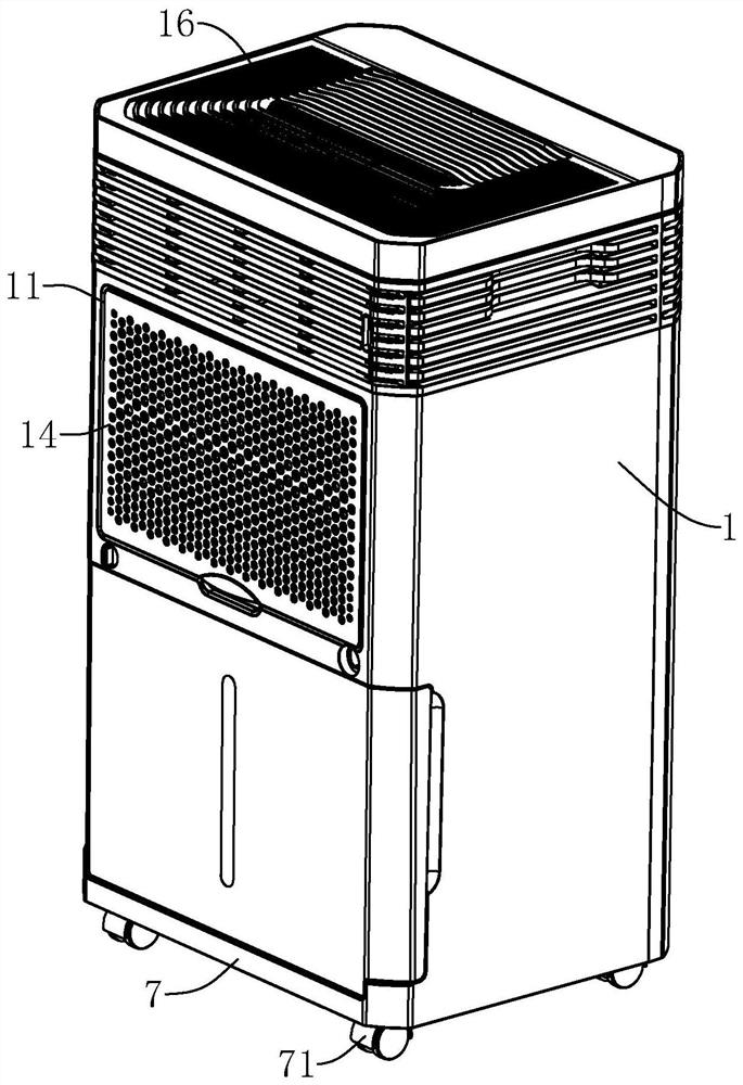
[0043] refer to figure 1 , the multifunctional dehumidifier includes a casing 1, a chassis 7 fixedly connected to the bottom of the casing 1, the side of the chassis 7 facing away from the casing 1 is fixedly connected to four universal casters 71, and the four universal casters 71 are fixed to the chassis 7 at the four corners.

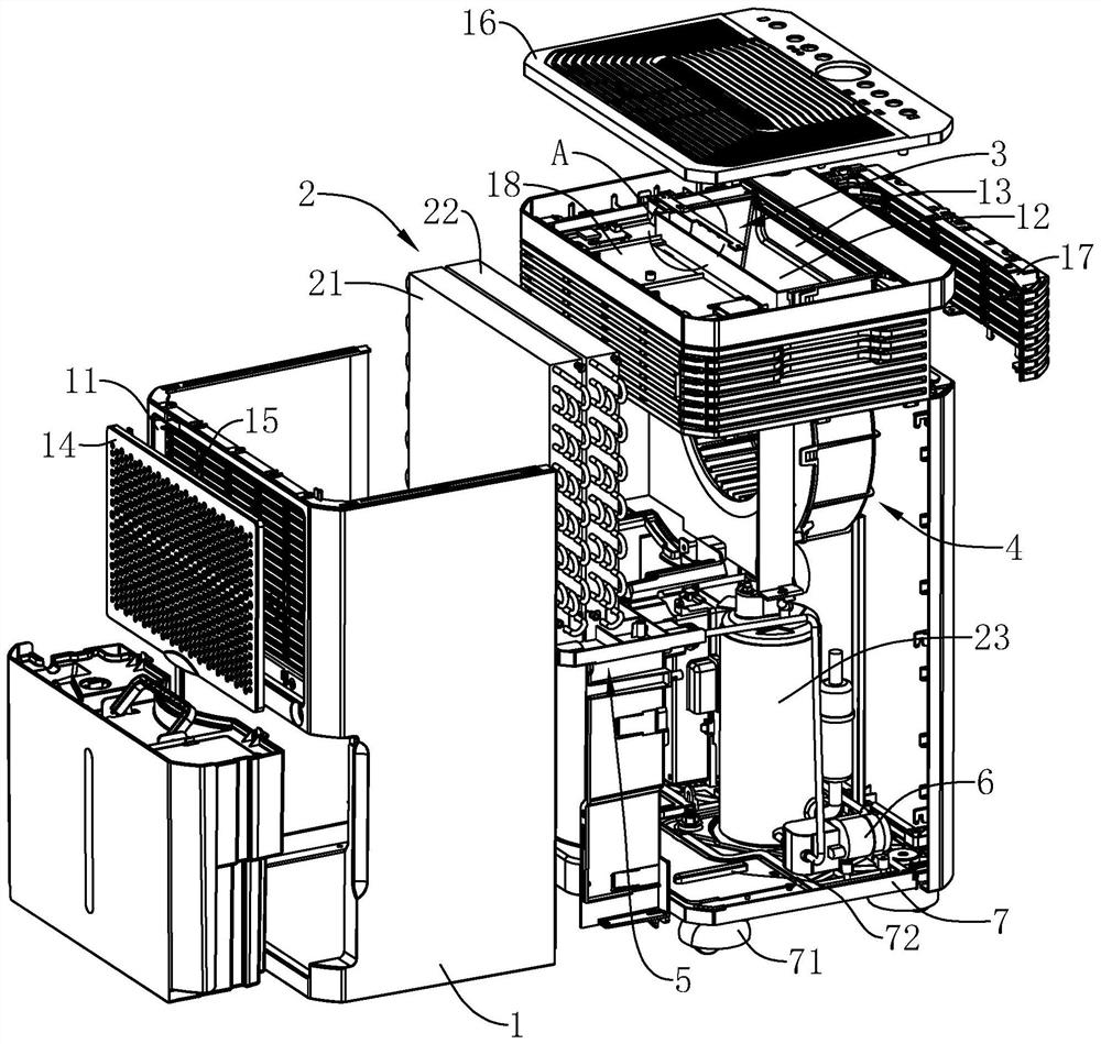
[0044] refer to figure 2 The side wall of the casing 1 away from the chassis 7 is provided with an air inlet 11, and the top of the casing 1 is located at a position away from the air inlet 11 and has a first air outlet 12, and the casing 1 is directed from the air inlet 11 to the first air outlet 12. The direction is provided with a moisture-proof device 2, a sterilizing device 3 and an air circulation device 4 in sequence, and the air circulation device 4 is lo...


PUM


Abstract

This application relates to a multifunctional dehumidifier, which includes a casing, an air inlet is opened on the side wall of the casing, a first air outlet is opened on the top of the casing, and an air circulation device is arranged in the casing below the first air outlet , the air circulation device is facing the direction of the air inlet, and the moisture-proof device and the sterilization device are arranged in sequence from the air inlet to the direction of the air circulation device in the casing. A number of ultraviolet lamp beads on the side of the air outlet. This application has the effect of reducing bacteria in humid air.

Description

technical field [0001] The present application relates to the field of dehumidifiers, in particular to a multifunctional dehumidifier. Background technique [0002] When the air is humid, it is easy to breed bacteria indoors. At the same time, there are some harmful microorganisms suspended in the air, which will have adverse effects on human health. Therefore, people generally use dehumidifiers to dry the air. [0003] The dehumidifier in the related art is composed of a compressor, a heat exchanger, an air circulation device, a water container, a casing and a controller. The casing is provided with an air inlet and a first air outlet. The humid air is sucked into the casing from the air inlet, and passes through the heat exchanger. At this time, the water molecules in the air condense into water droplets, and the treated dry air is discharged out of the casing through the first air outlet. This cycle keeps the indoor humidity at a suitable relative humidity. [0004] The...

Claims


Application Information

Patent Timeline
Patent Type & Authority Patents(China)
IPC IPC(8): F24F3/14F24F8/22F24F11/74F24F11/79H02K9/06
CPCF24F3/14F24F3/16F24F11/74F24F11/79H02K9/06Y02A50/20
Inventor 叶建荣潘振豪王辉巢则煌
Owner 宁波爱科特环境电器有限公司
Why Eureka
Try Eureka