Heat pump unit and heat pump water heater

A heat pump unit and heat exchanger technology, applied in heat pumps, fluid heaters, refrigerators, etc., can solve problems affecting users' daily life and poor user experience, and achieve the effect of improving user experience and reducing operating noise

Pending Publication Date: 2021-06-18
QINGDAO HAIER NEW ENERGY ELECTRIC APPLIANCE +2
1 Cites 0 Cited by

AI-Extracted Technical Summary

Problems solved by technology

[0004] However, since the heat pump unit is placed indoors and installed by hanging, the noise generated durin...

Method used

As a preferred embodiment, a mounting groove 15 is formed on the lower mounting surface of the base 1, and the electric control board 5 is arranged in the mounting groove 15; the base 1 is also provided with a cover plate (not shown in the figure) for the switch mounting groove 15 Show). Specifically, an installation groove 15 is formed on the lower installation surface of the base 1 to facilitate the installation and fixing of the electric control board 5 so that the electric control board 5 is embedded in the base 1 . At the same time, the installation groove 15 is covered by the cover plate, which can also protect the electric control board.
As a preferred embodiment, in order to improve the heat exchange efficiency of the heat exchanger 3, the heat pump unit also includes an air guide cover 8, the air guide cover 8 is arranged on the other end of the base 1, and the air guide cover 8 covers the The air outlet side of the heat exchanger 3 is also used to guide the airflow after heat exchange by the heat exchanger 3 to output outward. Specifically, under the action of the fan 4, the outside air enters the installation cavity and exchanges heat with the heat exchanger 3, and the airflow after the heat exchange enters the air guide 8 to be output through the air guide 8 Air after heat exchange. The air guide cover 8 is arranged on the air outlet side of the heat exchanger 3, and the air guide cover 8 can better guide the heat-exchanged airflow to the outside of the installation cavity, thereby preventing the heat-exchanged airflow from remaining in the installation chamber. The phenomenon of repeated heat exchange with the heat exchanger 3 occurs in the cavity, so that the heat exchange efficiency of the heat exchanger 3 can be improved more efficiently.
Embodiment five, as shown in Figure 4, in order to reduce the bad influence that the noise that compressor 2 and blower blower 4 operation produces causes to user. Then the base 1 is also provided with a casing 7 , which is installed on the base 1 and covers the compressor 2 , the heat exchanger 3 and the blower 4 . Specifically, an installation cavity is formed between the casing 7 and the base 1, and the compressor 2, the heat exchanger 3 and the fan 4 are all located in the relatively closed installation cavity. In this way, the noise generated during the operation of the compressor 2 and the fan 4 is effectively limited by the casing 7 to be transmitted outward, so as to reduce the operating noise. Preferably, the casing 7 adopts a casing with sound insulation function, for example: sound insulation cotton can be arranged in the casing 7 to achieve better sound insulation
In some embodiments, as shown in Figure 14, connector 822 can be connecting plate, and connecting plate is attached to the upper edge of water receiving tray 14, utilizes connecting plate to cooperate with the edge of water receiving tray 14 to realize strengthening The airtightness of the air outlet cavity. Preferably, the section of the connecting plate is an inverted U-shaped structure, so as to effectively increase the contact area between the connecting plate and the upper edge of the water receiving tray 14,
In some embodiments, in order to assemble conveniently, as shown in Figure 4 and Figure 9, then casing 7 is provided with mounting port 72, and mounting port 72 is connected with vent pipe 9, is formed in vent pipe 9 The air channel 91 and the air outlet channel 92, the air inlet channel 91 communicates with the installation cavity, and the air outlet channel 92 communicates with the air outlet cavity. The ventilation pipe 9 is used to communicate with the outside, so as to introduce outdoor air into the installation cavity, and output the heat-exchanged air to the outside. The air inlet channel 91 and the air outlet channel 92 are integrated in the ventilation pipe 9, which is more convenient for field operators to quickly assemble.
In some embodiments, the air inlet 1001 and the air outlet 1002 are arranged on the lower surface of the base 1, the air inlet 1001 is located at the air inlet side of the heat exchanger 3, and the air outlet 1002 is located at the air outlet of the heat exchanger 3 side. Arranging the air inlet 1001 and the air outlet 1002 directly on the lower surface of the base is more conducive to the smooth circulation of air between the installation cavity and the bathroom. In order to reduce the mutual influence of the airflow between the air inlet 1001 and the air outlet 1002, a recessed water receiving tray 14 is formed on the base 1, and the water receiving tray 14 is arranged between the air inlet 1001 and the air outlet 1002 to utilize The water receiving tray 14 separates the air inlet 1001 and the air outlet 1002 .
In some embodiments, the casing 7 is provided with a recessed structure 71 extending toward the direction of the base 1, the compressor 2 is located on one side of the recessed structure 71, and the heat exchanger 3 and the blower fan 4 are located in the recessed structure 71 the other side of the Specifically, the recessed structure 71 makes the area of ​​the casing 7 enclosing the auxiliary sound insulation cover 21 larger, which is more conducive to the effect of sound insulation and noise reduction. Moreover, since the recessed structure 71 can separate the compressor 2 from the heat exchanger 3 and the fan 4, the airflow generated by the fan 4 can more effectively perform heat exchange treatment on the heat exchanger 3, reducing the flow of airflow to the base 1 to install the compressor. The end of the machine 2 to improve the heat exchange efficiency of the airflow.
In some embodiments, the surface opposite to the wind guide cover 8 and the air inlet passage 91 can also be set as an arc-shaped wind guide surface 80, and the wind guide surface 80 is inclined toward the air outlet direction of the air inlet passage 91. Extend to the upper edge of the heat exchanger 3, so that the air introduced from the air inlet channel 91 can be guided to pass through the heat exchanger 3 through the air guide surface 80, so that the air entering the installation cavity can be smoothly passed from The air inlet side of the heat exchanger 3 passes through the heat exchanger 3 for heat exchange, so as to reduce the wind speed and improve the wind circulation efficiency, thereby improving the heat exchange efficiency.
In some embodiments, threaded thread can also be provided on the top of suspension rod 6, and the top of suspension rod 6 is threadedly connected with fastening nut 62; An expansion tube 63 is arranged, and the expansion tube 63 is located above the fastening nut 62 . Specifically, the upper end of the suspension rod 6, the fastening nut 62 and the expansion tube 63 form an expansion bolt structure, and then the suspension rod 6 can be directly fixed and installed in the concrete of the roof without additional installation functions, which simplifies the installation process , and reduce installation costs.
Two, under the situation of adopting outdoor air to carry out the air source of heat exchange as heat exchanger 3, as shown in Figure 9, heat pump unit also comprises air inlet channel 91 and air outlet channel 92, and air inlet channel 91 communicates with installation cavity body, and the air outlet channel 92 comm...

Abstract

The invention discloses a heat pump unit and a heat pump water heater. The heat pump unit comprises a base, a compressor, a heat exchanger, a fan and a first noise enclosure; an installation part used for suspended installation is arranged on the base; the compressor is mounted on the base; the heat exchanger is mounted on the base; the fan is mounted on the base and used for driving airflow to exchange heat through the heat exchanger; and the first noise enclosure is mounted on the base and covers the compressor, the heat exchanger and the fan. According to the heat pump unit and the heat pump water heater, noise generated in the operation process of the compressor and the fan is effectively limited in a noise enclosing cavity formed between the first noise enclosure and the base, so that the operation noise of the heat pump unit is effectively lowered, and the user experience is improved.

Application Domain

Technology Topic

Image

  • Heat pump unit and heat pump water heater
  • Heat pump unit and heat pump water heater
  • Heat pump unit and heat pump water heater

Examples

  • Experimental program(7)

Example Embodiment

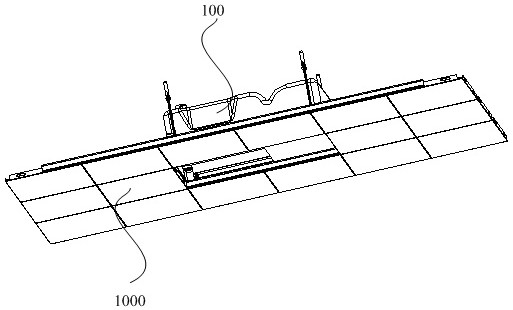
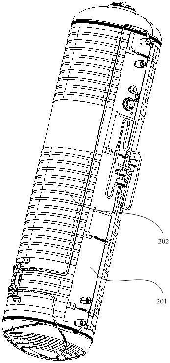
[0042] Embodiment one, such as figure 1 and figure 2 As shown, the present invention provides a heat pump water heater, which generally includes a heat pump unit 100 and a water tank 200 . The basic components of the heat pump unit 100 are a base, a compressor installed on the base, a heat exchanger, a throttling device and a fan, and the water tank 200 includes an outer shell (not shown), an inner tank 201 and an auxiliary heat exchanger 202. The compressor, the heat exchanger, the throttling device and the auxiliary heat exchanger 202 are connected to form a refrigerant circulation flow path, and the water in the inner tank 201 is heated and treated by using the principle of a heat pump. The above is the basic configuration of a conventional heat pump water heater, and will not be limited or repeated here.
[0043] During actual installation and use, the heat pump unit 100 is fixed on the indoor roof by means of hanging installation, and is hidden on the ceiling 1000 . The water tank 200 is placed in the user's home in a conventional installation manner.
[0044] For the heat pump unit 100 to meet the requirements of hanging and concealed installation, it is necessary to make corresponding improvements in terms of the layout of its internal components, the hanging installation of the overall equipment, and the way of air circulation. The details are described below with reference to the drawings.

Example Embodiment

[0045] Embodiment two, such as image 3 and Figure 4 As shown, in order to effectively reduce the overall height of the heat pump unit to meet the hidden installation of the heat pump unit in the ceiling. The heat pump unit includes: a base 1 , a compressor 2 , a heat exchanger 3 and a fan 4 . In order to meet the requirements of hanging installation, the base 1 is provided with a mounting part 10 for hanging installation on the base 1; the heat exchanger 3 is arranged on the base 1; the fan 4 is used to drive airflow through the heat exchanger 3 Perform heat exchange. Wherein, in order to effectively reduce the overall height of the heat pump unit, the compressor 2 is arranged horizontally and installed on the base 1 ; the fan 4 and the heat exchanger 3 are located on the same side of the compressor 2 .
[0046] Specifically, the compressors 2 in the heat pump unit are horizontally arranged and fixedly installed on the base 1 . In this way, the height space occupied by the compressor 2 can be effectively reduced, so as to effectively reduce the overall height of the heat pump unit. At the same time, the fan 4 and the heat exchanger 3 are located on the same side of the compressor 2, so that the fan 4 mainly blows or sucks the heat exchanger 3, so as to reduce the overall size of the fan 4 and prevent the fan 4 from causing the height of the heat pump unit to increase. increase.
[0047]In some embodiments, for the convenience of installing the compressor 2, such as Image 6 As shown, one end of the base 1 is provided with an installation platform 11 , and the compressor 2 is arranged on the installation platform 11 . Specifically, the compressor 2 is horizontally installed and fixed on the installation platform 11 , and the installation platform 11 is located at one end of the base 1 , so that the compressor 2 is arranged at a corresponding end of the base 1 . Preferably, in order to reduce the impact of vibration caused by the operation of the compressor 2, the installation platform 11 is provided with an installation bracket 12, and a vibration damping pad 13 is also arranged between the installation bracket 12 and the installation platform 11, and the compressor 2 is installed on the installation bracket 12 superior.
[0048] Wherein, for the mounting bracket 12, in order to be able to cooperate with the vibration damping pad 13 to achieve a better vibration damping effect, the mounting platform 11 is provided with two mounting brackets 12 arranged side by side. The mounting bracket 12 has a fixed part 121 and is distributed on The tilting parts 122 on both sides of the fixing part 121, the fixing part 121 is fixed on the installation platform 11, and the vibration damping pad 13 is arranged between the tilting part 122 and the installation platform 11; wherein, the compressor 2 is fixed on the tilting part 122 . Specifically, the mounting bracket 12 is usually processed by sheet metal parts, which has a certain degree of elasticity, and the compressor 2 is installed on the raised portion 122, and the bottom of the raised portion 122 is pressed on the damping pad 13. The elasticity of the installation bracket 12 and the elasticity of the damping pad 13 can better dampen the vibration of the compressor 2 . Meanwhile, in a certain embodiment, in order to improve the structural strength of the base 1 to install and fix the compressor 2 , the lower surface of the installation platform 11 is provided with several reinforcing ribs 111 arranged in a staggered manner.
[0049] In some embodiments, in order to facilitate the installation of the heat exchanger 3 and meet the requirements of the overall height of the equipment, the other end of the base 1 forms a water receiving tray 14 , and the heat exchanger 3 is arranged above the water receiving tray 14 . Specifically, in actual use, the heat exchanger 3 is used for evaporative heat exchange, so condensed water will be generated on the surface of the heat exchanger 3, and the condensed water will flow into the water receiving tray 14 under the heat exchanger 3 under the action of gravity middle. The drain pan 14 is provided with a drain pipe 141 and is discharged to the outside through the drain pipe 141 . Wherein, a downwardly recessed water receiving tray 14 is formed on the base 1, and the heat exchanger 3 is arranged in the water receiving tray 14, so that the installation height of the heat exchanger 3 on the base 1 can be reduced more effectively , so that a larger-sized heat exchanger 3 can be used to improve heat exchange efficiency.
[0050] As a preferred embodiment, in order to effectively improve the heat exchange capacity of the heat exchanger 3 without increasing the height, the length dimension of the heat exchanger 3 is greater than the height dimension of the heat exchanger 3, so that the heat exchanger 3 along the The length direction of the base 1 is distributed, and the length direction of the base 1 is fully utilized to increase the heat exchange area of ​​the heat exchanger 3 .

Example Embodiment

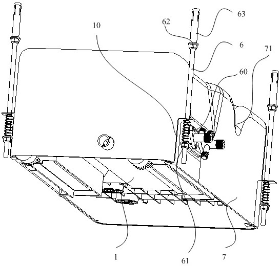
[0051] Embodiment three, such as Figure 7 As shown, since the heat pump unit is hung and installed on the indoor roof, in order to facilitate the operator to maintain the electronic control devices later, for the base 1, the upper surface of the base 1 forms the upper mounting surface, and the lower surface of the base 1 Form the lower mounting surface. Wherein, the compressor 2, the heat exchanger 3 and the fan 4 are installed on the upper installation surface of the base 1; lower mounting surface.
[0052] After the heat pump unit is hung and installed, since the electric control board 5 is installed on the lower mounting surface of the base 1, when the electric control board 5 needs to be repaired, it is only necessary to open the ceiling to face the electric control board 5 at the bottom of the base 1. Make repairs. Wherein, for the specific configuration of the electric control board 5 , reference may be made to the control circuit board in a conventional heat pump unit, and no limitation or description is made here.
[0053] As a preferred embodiment, an installation groove 15 is formed on the lower installation surface of the base 1 , and the electric control board 5 is disposed in the installation groove 15 ; a cover plate (not shown) for the switch installation groove 15 is also provided on the base 1 . Specifically, an installation groove 15 is formed on the lower installation surface of the base 1 to facilitate the installation and fixing of the electric control board 5 so that the electric control board 5 is embedded in the base 1 . At the same time, the installation groove 15 is covered by the cover plate, which can also protect the electric control board.
[0054] In some embodiments, the compressor 2 can also be arranged at the upper part of the installation groove 15, so that wiring between the electric control board 5 and the compressor 2 on the top is more convenient. For the reinforcing rib 111, it is formed in the installation groove 15, and the electric control board 5 is supported by the reinforcing rib 111. On the one hand, it is convenient to fix the electric control board 5 on the reinforcing rib 111 by screws; on the other hand, the reinforcing rib 111 supports the electric control board 5, and the reinforcing ribs 111 are also conducive to dissipating the released heat of the electric control board 5, so as to ensure the reliable operation of the electric control board.

PUM

no PUM

Description & Claims & Application Information

We can also present the details of the Description, Claims and Application information to help users get a comprehensive understanding of the technical details of the patent, such as background art, summary of invention, brief description of drawings, description of embodiments, and other original content. On the other hand, users can also determine the specific scope of protection of the technology through the list of claims; as well as understand the changes in the life cycle of the technology with the presentation of the patent timeline. Login to view more.

Similar technology patents

Classification and recommendation of technical efficacy words

  • Reduce running noise
  • Improve user experience

Air channel structure and air conditioner

InactiveCN105546777AGuaranteed heat exchange and heat exchange effectReduce running noiseDucting arrangementsLighting and heating apparatusAerospace engineeringAir channel
Owner:GREE ELECTRIC APPLIANCES INC
Why Eureka
Try Eureka