Gradient corrugated flow field structure
A corrugated, flow field technology, applied in the field of fuel cells, can solve problems such as cost bottlenecks, restrictions on large-scale applications, and high processing precision requirements, and achieve the effect of avoiding dead zones and liquid water accumulation
- Summary
- Abstract
- Description
- Claims
- Application Information
AI Technical Summary
Problems solved by technology
Method used
Image
Examples
Embodiment 1
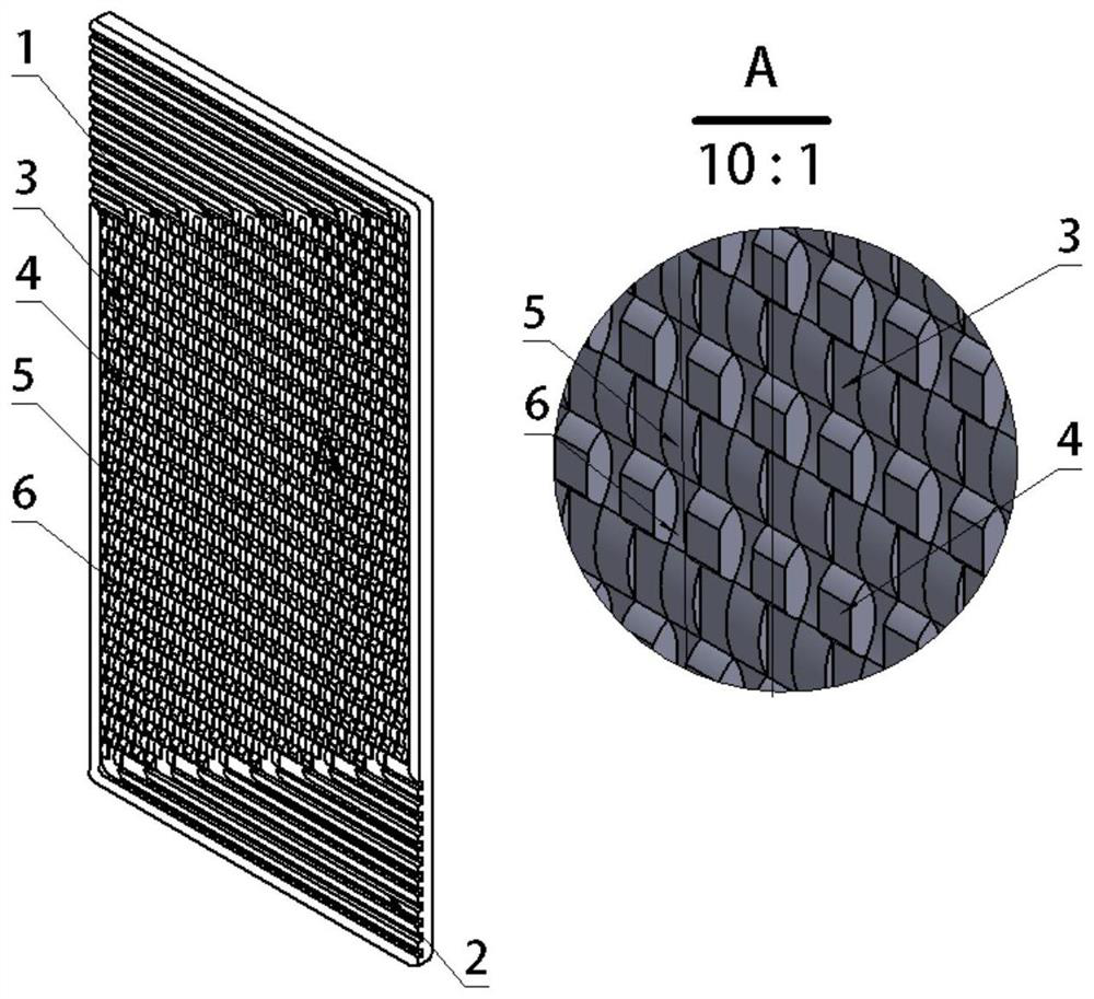
[0027] A gradient corrugated flow field structure, the flow field structure includes a plurality of inlet manifolds 1, a plurality of outlet manifolds 2, and a central area between the inlet manifolds 1 and the outlet manifolds 2;
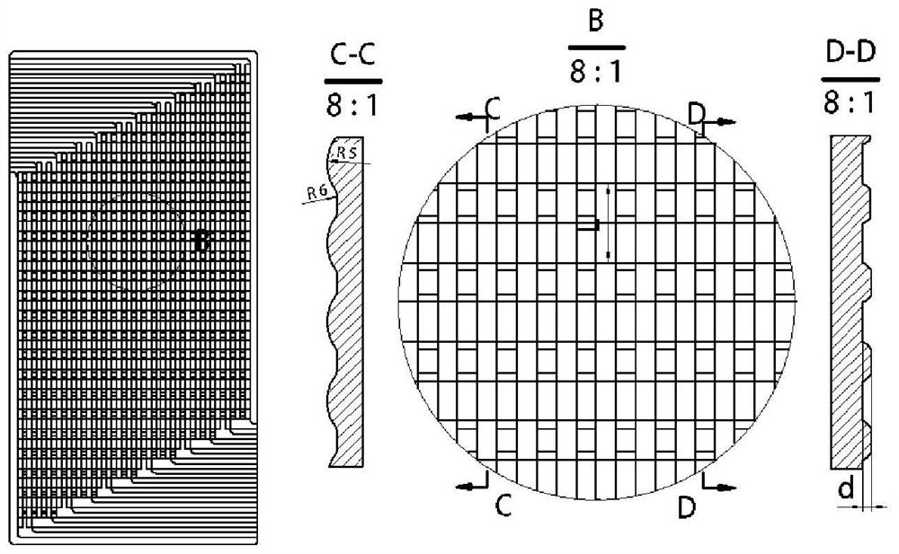
[0028] The central area is composed of multiple primary flow channels and multiple secondary flow channels alternately, and the primary flow channels and secondary flow channels are arranged in parallel;
[0029] The first-stage flow channel is formed alternately by a plurality of identical concave arc surfaces 6 and a plurality of identical convex arc surfaces 5, the radius of the concave arc surfaces 6 is 2mm, and the radius of the convex arc surfaces 5 is It is equal to the radius of the concave arc surface 6, and the height of the convex arc surface 5 is equal to the height of the concave arc surface 6;
[0030] The secondary flow channel is composed of a plurality of identical convex arc-like surfaces 4 with flat tops and a plurality of identi...
Embodiment 2
[0037] A gradient corrugated flow field structure, the flow field structure includes a plurality of inlet manifolds 1, a plurality of outlet manifolds 2, and a central area between the inlet manifolds 1 and the outlet manifolds 2;
[0038] The central area is composed of multiple primary flow channels and multiple secondary flow channels alternately, and the primary flow channels and secondary flow channels are arranged in parallel;
[0039] The first-stage flow channel is formed alternately by a plurality of identical concave arc surfaces 6 and a plurality of identical convex arc surfaces 5, the radius of the concave arc surfaces 6 is 2mm, and the radius of the convex arc surfaces 5 is It is equal to the radius of the concave arc surface 6, and the height of the convex arc surface 5 is equal to the height of the concave arc surface 6;
[0040] The secondary flow channel is composed of a plurality of identical convex arc-like surfaces 4 with flat tops and a plurality of identi...
Embodiment 3
[0047] A gradient corrugated flow field structure, the flow field structure includes a plurality of inlet manifolds 1, a plurality of outlet manifolds 2, and a central area between the inlet manifolds 1 and the outlet manifolds 2;
[0048] The central area is composed of multiple primary flow channels and multiple secondary flow channels alternately, and the primary flow channels and secondary flow channels are arranged in parallel;
[0049] The first-stage flow channel is formed alternately by a plurality of identical concave arc surfaces 6 and a plurality of identical convex arc surfaces 5, the radius of the concave arc surfaces 6 is 2mm, and the radius of the convex arc surfaces 5 is It is equal to the radius of the concave arc surface 6, and the height of the convex arc surface 5 is equal to the height of the concave arc surface 6;
[0050] The secondary flow channel is composed of a plurality of identical convex arc-like surfaces 4 with flat tops and a plurality of identi...
PUM
| Property | Measurement | Unit |
|---|---|---|
| radius | aaaaa | aaaaa |
| height | aaaaa | aaaaa |
Abstract
Description
Claims
Application Information
 - R&D
- Intellectual Property
- Life Sciences
- Materials
- Tech Scout
- Unparalleled Data Quality
- Higher Quality Content
- 60% Fewer Hallucinations
Browse by: Latest US Patents, China's latest patents, Technical Efficacy Thesaurus, Application Domain, Technology Topic, Popular Technical Reports.
© 2025 PatSnap. All rights reserved.Legal|Privacy policy|Modern Slavery Act Transparency Statement|Sitemap|About US| Contact US: help@patsnap.com


