
Movable power transformation cabinet with good shock absorption

A mobile and transformer cabinet technology, applied in the field of transformer cabinets, can solve the problems of manpower and working hours, damage of electrical components of transformer cabinets, circuit failures, etc., to save manpower and working hours, strong stability, and ensure stable installation sexual effect

Pending Publication Date: 2021-06-18
常州峰林电气有限公司
View PDF0 Cites 0 Cited by
  • Summary
  • Abstract
  • Description
  • Claims
  • Application Information

AI Technical Summary

Problems solved by technology

[0003] In the prior art, the installation of the transformer cabinet requires manual handling, which consumes manpower and man-hours. However, the installation of universal wheels at the bottom of the transformer cabinet will affect the installation stability of the cabinet body, and the transformer cabinet is often used when it is in use. It will vibrate due to external interference, and in severe cases, it will damage the electrical components inside the transformer cabinet, resulting in circuit failure

Method used


Image

  • Movable power transformation cabinet with good shock absorption
  • Movable power transformation cabinet with good shock absorption

Examples


Embodiment 1

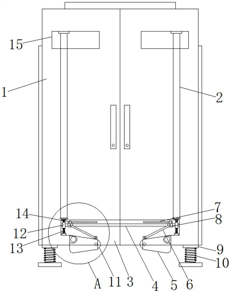
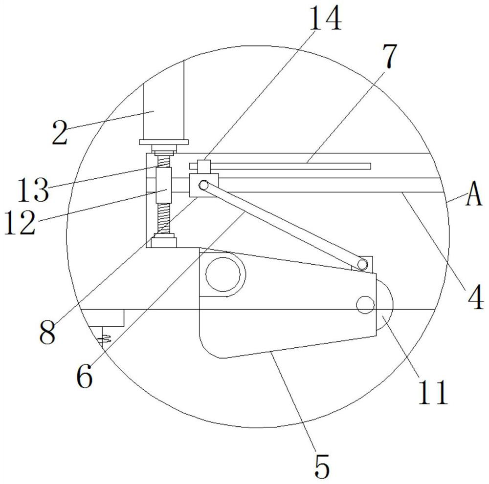
[0020] Embodiment 1, when the equipment is being transported, the user can turn the adjustment rod 2 in the square groove 15, the adjustment rod 2 drives the worm 13 to rotate at the same time, the worm 13 drives the worm wheel 12 to drive the lead screw 4 to rotate, and the rotation of the lead screw 4 makes the The moving block 8 assembled on the lead screw 4 slides to the middle, and the moving block 8 will drive the connecting rod 6 on one side to rotate, and use the change of the length of the connecting rod 6 on the Z axis to push the rotating plate 5 to open. When the sliding block 14 slides to At the end of the chute 7, the chute 7 limits the position of the moving block 8. At this time, the universal wheels 11 support the cabinet body 1, and the user can easily carry the cabinet body 1. It should be noted that, The worm gear 12 and the worm screw 13 have self-locking characteristics when they are installed and designed. When the adjustment rod 2 is not turned, the univ...

Embodiment 2

[0022] Embodiment 2, after the installation of the cabinet body 1 is completed, the shock absorbing spring 10 can effectively reduce and absorb the vibration received on the cabinet body 1, so that the cabinet body 1 is in a stable operating state, ensuring the safe operation of the cabinet body 1 and avoiding accidents circuit failure occurs.


PUM


Abstract

The invention relates to the technical field of power transformation cabinets, in particular to a movable power transformation cabinet with good shock absorption. The movable power transformation cabinet solves the defects of labor and time consumption and easy vibration in the prior art, and comprises a cabinet body; the cabinet body is respectively provided with a groove, a through hole and a square groove, and the interiors of the groove, the through hole and the square groove are communicated with each other; a lead screw and a worm are rotationally installed in the groove; a moving block is arranged outside the lead screw in a sliding mode; a connecting rod is movably hinged to one side of the moving block; and through arrangement of structures such as an adjusting rod, a worm gear, the worm, the sliding block, the moving block, the connecting rod and a rotating plate and the like, universal wheels facilitating moving and carrying of the cabinet body are additionally arranged at the bottom of the cabinet body; during carrying, a user can adjust the universal wheels to be unfolded, so that carrying operation of personnel is facilitated, and manpower and working hours are saved; and the universal wheels can be folded during installation, the installation stability of the cabinet body is ensured, and use of the personnel is facilitated.

Description

technical field [0001] The invention relates to the technical field of transformer cabinets, in particular to a movable transformer cabinet with good shock absorption. Background technique [0002] The substation cabinet is the box in the place where the voltage and current of electric energy are transformed, concentrated and distributed. In order to ensure the quality of electric energy and the safety of equipment, voltage adjustment, power flow (power system The flow direction and distribution of voltage, current and power in each node and branch in the network) control and protection of transmission and distribution lines and main electrical equipment. Mainly used to protect power facilities. [0003] In the prior art, the installation of the transformer cabinet requires manual handling, which consumes manpower and man-hours. However, the installation of universal wheels at the bottom of the transformer cabinet will affect the installation stability of the cabinet body, ...

Claims


Application Information

Patent Timeline
IPC IPC(8): H02B1/54H02B1/52H02B1/30
CPCH02B1/303H02B1/52H02B1/54
Inventor 眭银峰陆亚东
Owner 常州峰林电气有限公司
Learn More