Rotary friction nanometer generator

A nano-generator, rotary technology, applied in the energy field, can solve the problems of inability to realize energy collection and detection, low conversion efficiency, incomplete contact, etc., and achieve the effect of improving power conversion efficiency

Pending Publication Date: 2021-06-18
GUANGDONG OCEAN UNIVERSITY
View PDF0 Cites 3 Cited by
  • Summary
  • Abstract
  • Description
  • Claims
  • Application Information

AI Technical Summary

Problems solved by technology

Therefore, when two uncharged objects rub against each other, they will be charged. Triboelectricity is one of the most common phenomena in nature. By rubbing objects against each other, one side will be charged negatively, and the other side will be negatively charged. It is positively charged, but triboelectricity is difficult to collect and utilize, so it is often ignored. In the prior art, a transparent flexible triboelectric generator has been developed. The triboelectric nanogenerator can not only be used to collect the original Various forms of mechanical energy are wasted (harvesting ocean energy, wind energy, vibration energy, etc.), and can also be used as a self-driven sensor to detect mechanical signals, however, the existing friction generator works on the working principle of the generator During the process, the friction surface is formed between the polymer and the metal electrode, or between the polymers. The friction surface needs to be in constant contact and separation, but due to the roughness of the material surface, the contact is incomplete, resulting in conversion The efficiency is very low, and the functions of energy harvesting and detection cannot be realized

Method used


Image

  • Rotary friction nanometer generator
  • Rotary friction nanometer generator
  • Rotary friction nanometer generator

Examples


Embodiment 1

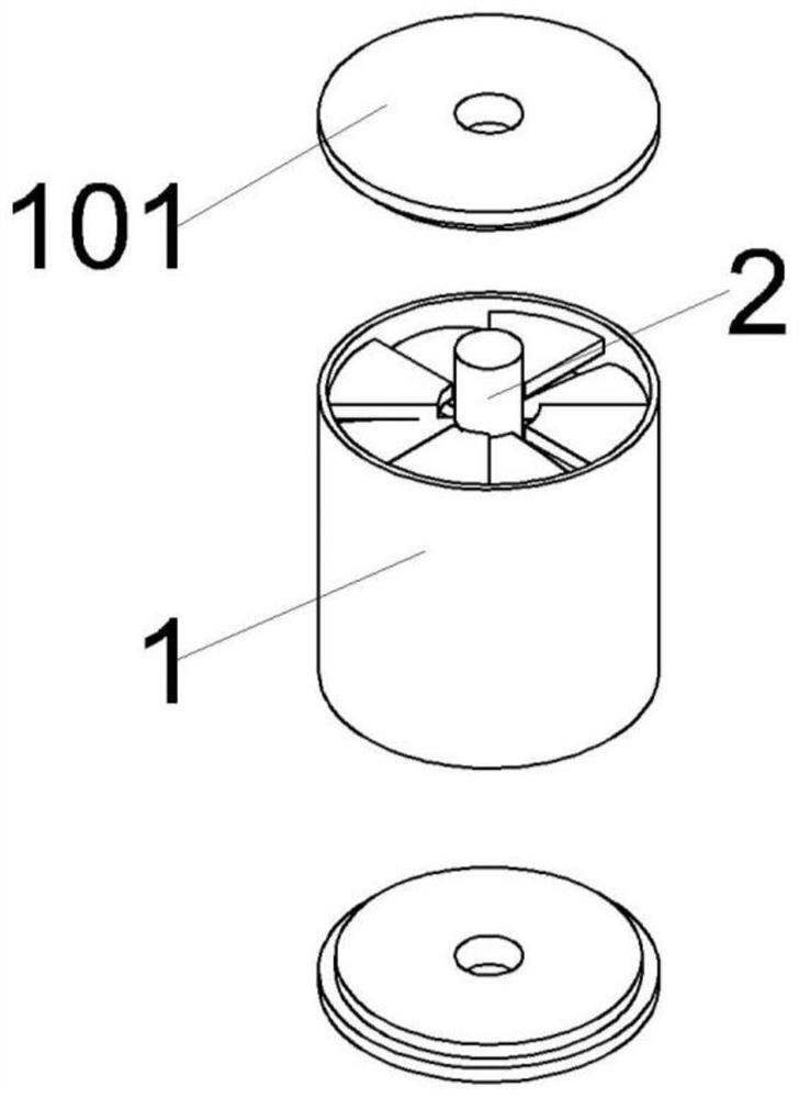
[0032] refer to Figure 1-6 As shown, this embodiment provides a rotary friction nanogenerator, including a housing 1, an end cover 101 fixedly connected to both ends of the housing 1, and a rotating shaft 2 connected to the center of the end cover 101 for rotation;

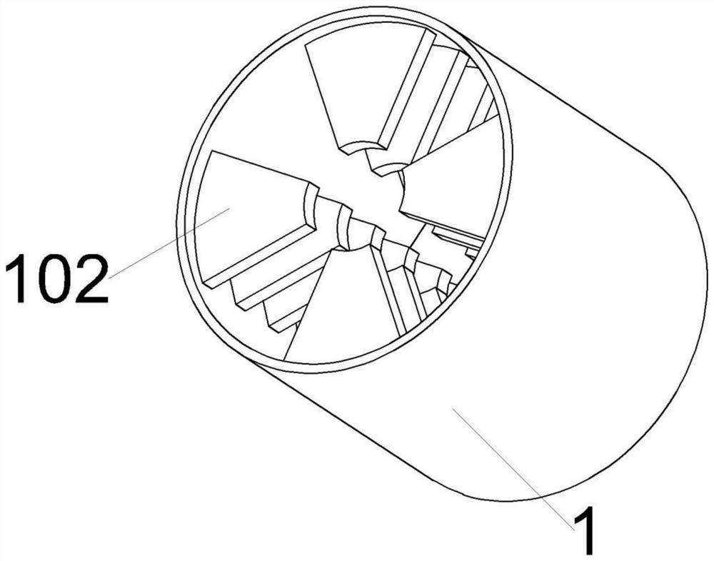
[0033] The inner wall of the housing 1 is axially fixedly connected with several layers of friction parts, and the friction parts include a number of first friction plates 102 arranged at equal intervals;

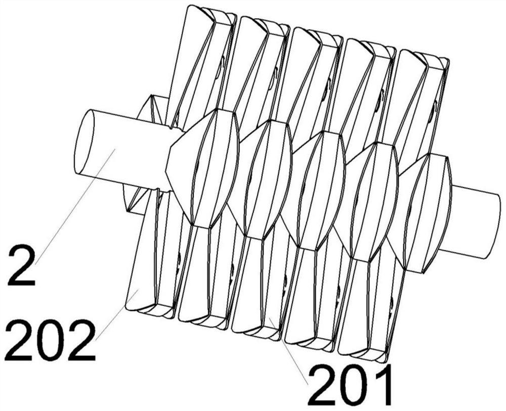
[0034] The circumferential side wall of the rotating shaft 2 is fixedly connected with several layers of self-generating friction parts. The self-generating friction part includes a self-generating component and a second friction plate 202 elastically connected to the upper and lower ends of the self-generating component. Two first friction plates located above and below The sheet 102 is in contact with the second friction sheet 202;

[0035] The rotating shaft 2 is provided with a conductive part, and the se...

Embodiment 2

[0048] The difference between the nanogenerator in this embodiment and the first embodiment is that the power output device is a signal processor. The first friction plate 102 and the wire 3 are respectively electrically connected to the signal processor. By setting the signal processor, the nanogenerator can be used for sensor detection. The signal processor is an existing technology in the field and will not be repeated here.

Embodiment 3

[0050] refer to Figure 7-8 As shown, the difference between the nanogenerator of this embodiment and the first embodiment is that the side where the first friction plate 102 contacts the second friction plate 202 is provided with an arc-shaped groove, and the center of the arc-shaped groove is aligned with the rotating shaft 2 The center of the circle coincides, and the side of the second friction plate 202 in contact with the first friction plate 102 is fixedly connected with an arc-shaped protrusion 2021. The center of the arc-shaped protrusion 2021 coincides with the center of the circle of the rotating shaft 2. The widths of the arc-shaped protrusions 2021 are matched, and the two ends of the arc-shaped protrusions 2021 are provided with edge angles. The radius of the arc-shaped grooves on the first friction plate 102 is the same, and the radii of the arc-shaped protrusions 2021 on the adjacent second friction plates 202 are different. The radius of the adjacent arc-shape...


PUM


Abstract

The invention belongs to the field of energy and relates to a rotary friction nanometer generator. The rotary friction nanometer generator comprises a shell and end covers fixedly connected to the two ends of the shell; the centers of the end covers are rotationally connected with a rotating shaft; a plurality of layers of friction parts are fixedly connected to the inner side wall of the shell in the axial direction, and each friction part comprises a plurality of first friction plates arranged at equal intervals; the circumferential side wall of the rotating shaft is fixedly connected with a plurality of layers of self-power-generation friction parts; each self-power-generation friction part comprises a self-power-generation assembly and second friction plates elastically connected to the upper end and the lower end of the self-power-generation assembly; the two first friction plates located above and below the corresponding second friction plate respectively contact with the second friction plate; a conductive part is arranged on the rotating shaft; the self-generating assemblies and the conductive part are electrically connected with an electric energy output device; and the first friction plates are electrically connected with the electric energy output device; and the two first friction plates which are adjacent in a vertical direction contact with the corresponding second friction plate. The friction nanometer generator provided by the invention has high energy conversion efficiency.

Description

technical field [0001] The invention relates to the energy field, in particular to a rotary friction nanometer generator. Background technique [0002] Electrification by friction is the result of the transfer of electrons from one object to another, so that both objects are charged with an equal amount of charge. Objects that gain electrons are negatively charged, and objects that lose electrons are positively charged. Therefore, when two uncharged objects rub against each other, they will be charged. Triboelectricity is one of the most common phenomena in nature. By rubbing objects against each other, one side will be charged negatively, and the other side will be negatively charged. It is positively charged, but triboelectricity is difficult to collect and utilize, so it is often ignored. In the prior art, a transparent flexible triboelectric generator has been developed. The triboelectric nanogenerator can not only be used to collect the original Various forms of mecha...

Claims


Application Information

Patent Timeline
Patent Type & Authority Applications(China)
IPC IPC(8): H02N1/04H02J7/32
CPCH02J7/32H02N1/04
Inventor 赵志强王岩潘新祥袁剑平毛鸿飞贾宝柱徐进徐敏义庞洪臣钟英豪黄喜利魏斌
Owner GUANGDONG OCEAN UNIVERSITY
Why Eureka
Try Eureka