

Base station and cleaning robot system
Patent Information
- Authority / Receiving Office
- CN · China
- Patent Type
- Applications(China)
- Current Assignee / Owner
- SHENZHEN SILVER STAR INTELLIGENT TECH CO LTD
- Publication Date
- 2021-06-22
Smart Images
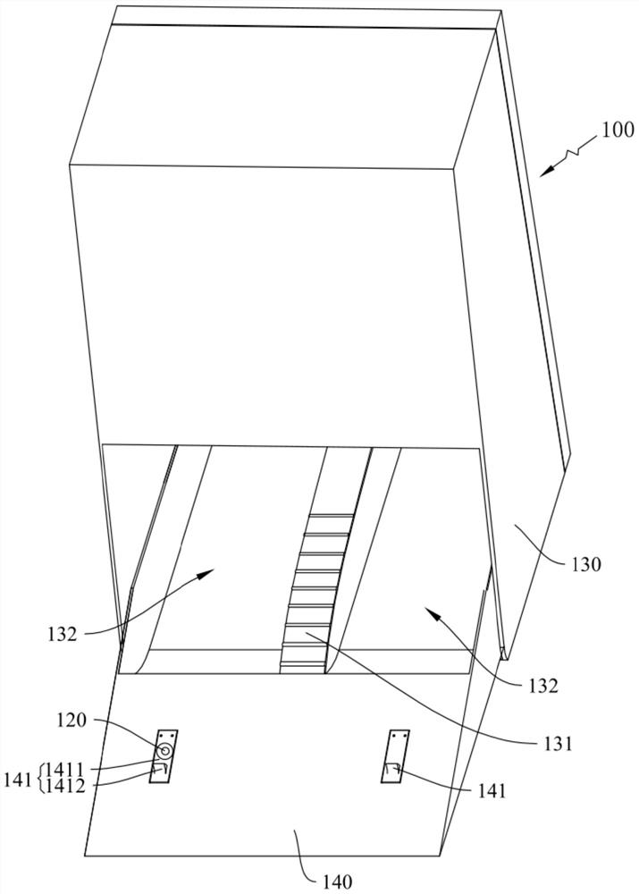
Figure 1 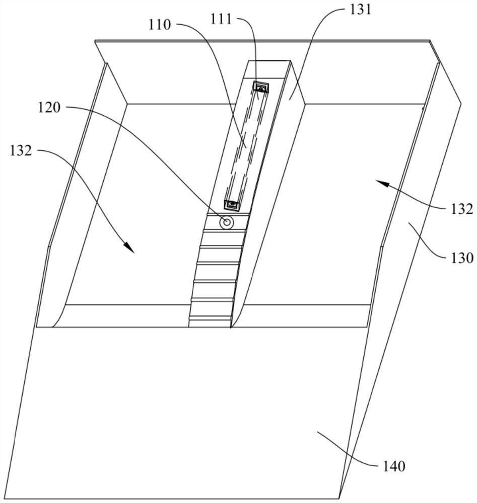
Figure 2 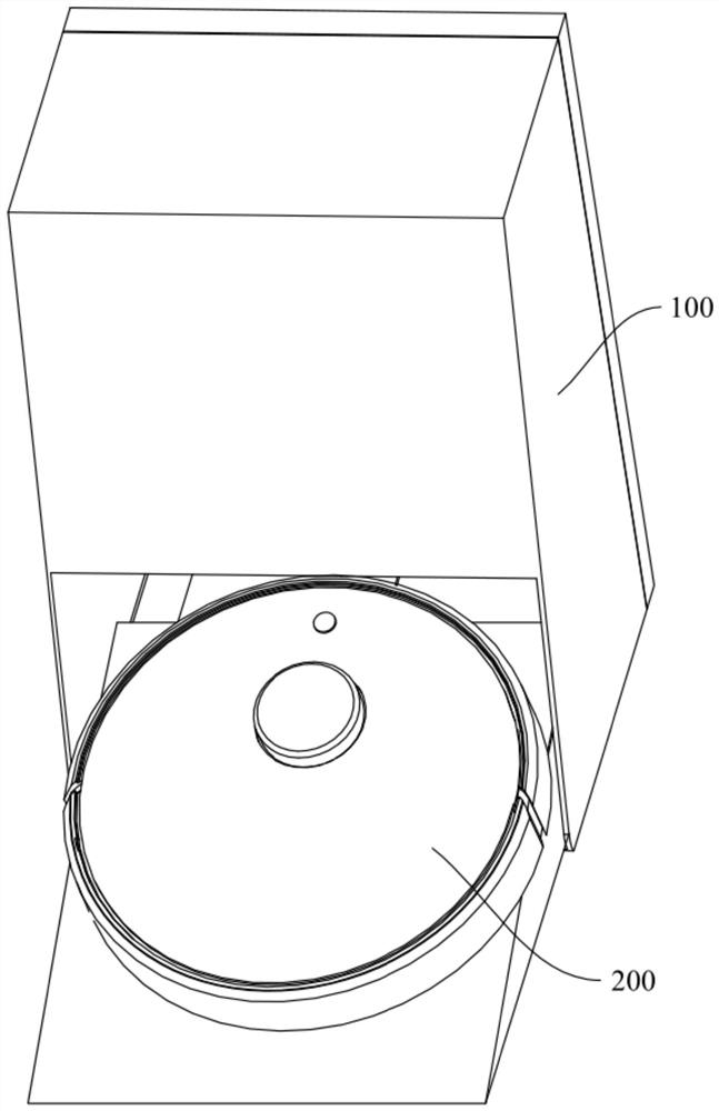
Figure 3
Abstract
Description
technical field
[0001] The invention belongs to the technical field of cleaning robots, and in particular relates to a base station and a cleaning robot system. Background technique
[0002] The cleaning robot can move relatively smoothly through at least two walking wheels, and drive the cleaning cloth at the bottom to realize the mopping and cleaning operation. After a period of operation, the cleaning cloth will be contaminated with impurities such as stains and dust. In this regard, in related industries, operations such as cleaning the cleaning cloth are usually performed through the base station. However, the functional components such as the cleaning mechanism and disinfection components of the existing base stations are manually opened and closed, which is poor in timeliness and easily causes energy waste. Contents of the invention
[0003] The purpose of the embodiments of the present invention is to provide a base station to solve the technical problem that each...