Machining device for electric tool sawteeth

A technology of electric tools and processing devices, which is applied in the direction of tool manufacturing, manufacturing tools, metal processing equipment, etc. of sawing machine devices, and can solve the problems of affecting the sawtooth punching accuracy, unable to adjust the punching, and difficult sawtooth, so as to improve the utilization rate of equipment , Increase the scope of use, enhance the stability of the effect

Inactive Publication Date: 2021-06-22
东莞市鸿安自动化科技有限公司
View PDF0 Cites 0 Cited by
  • Summary
  • Abstract
  • Description
  • Claims
  • Application Information

AI Technical Summary

Problems solved by technology

[0002] The chainsaw, also known as the "power saw", was invented by the German Andreas Steele in 1926, which greatly saved the time and manpower spent on cutting materials. The chainsaw uses electricity as power for Cutting tools for cutting wood, stone, steel, etc. have sharp teeth on the edge, which are divided into fixed and portable. The saw blade is generally made of tool steel, and there are many types such as round, strip and chain. 1. Currently sawtooth Punching the blank center hole is an indispensable and important link in the sawtooth processing, but the existing gear center hole punching equipment still has some deficiencies in use. The sawtooth is not fixed firmly during the punching process, which affects the sawtooth punching. 2. The existing sawtooth grinding is difficult to operate. Generally, the grinding wheel is fixed. Manually adjust the height and position of the sawtooth and then adjust the rotation of the sawtooth, so as to improve the quality of the sawtooth. Grinding operation for each sawtooth of the electric tool, the adjustment operation is troublesome, and the work efficiency is low; therefore, we propose a new processing device for electric tool sawtooth

Method used


Image

  • Machining device for electric tool sawteeth
  • Machining device for electric tool sawteeth
  • Machining device for electric tool sawteeth

Examples


Embodiment 1

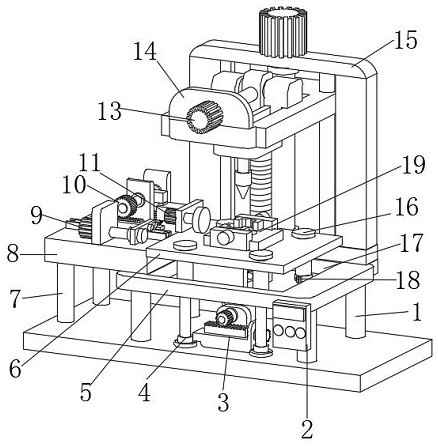
[0033] A processing device for electric tool sawtooth, such as figure 1 As shown, including the No. 1 stabilizing plate 5, the four corners of the lower end of the No. 1 stabilizing plate 5 are all fixedly connected with a No. 1 support column 1, the front right part of the No. 1 stabilizing plate 5 is fixedly connected with the control box 2, and the upper end of the No. 1 stabilizing plate 5 The middle part has groove 17, and No. 1 stable plate 5 is provided with moving plate 6 directly above, and the four corners of the upper end of moving plate 6 are all socketed with No. 1 limit rod 16, and the outer surface lower parts of four No. 1 limit rods 16 are A No. 1 limit block 18 is socketed, and the lower ends of the four No. 1 limit rods 16 are fixedly connected with a No. 1 stable block 4, and the middle part of the upper end of the mobile plate 6 is fixedly connected with a clamping device 19, and the lower end front of the mobile plate 6 is connected with the The rear part...

Embodiment 2

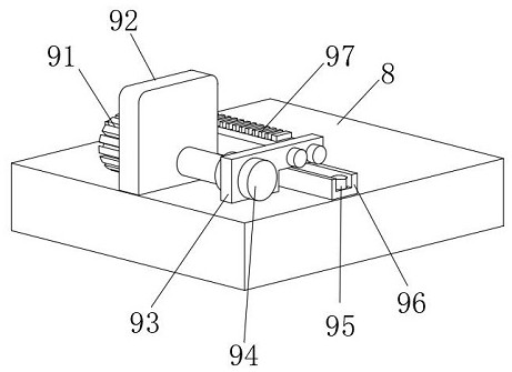
[0036] On the basis of Example 1, as Figure 2-3 As shown, a processing device for sawtooth electric tools includes a No. 1 stabilizing plate 5, which is characterized in that: the four corners of the lower end of the No. 1 stabilizing plate 5 are fixedly connected with a No. 1 support column 1, and the front right part of the No. 1 stabilizing plate 5 is fixed. A control box 2 is connected, a groove 17 is provided in the middle part of the upper end of the No. 1 stable plate 5, a movable plate 6 is arranged directly above the No. 1 stable plate 5, and a No. 1 limit rod 16 is sleeved on the four corners of the upper end of the movable plate 6. The outer surface bottoms of four No. 1 limit rods 16 are all sleeved with a No. 1 limit block 18, and the lower ends of the four No. 1 limit rods 16 are all fixedly connected with a No. 1 stable block 4, and the middle part of the upper end of the mobile plate 6 is fixedly connected with a Clamping device 19, the lower front portion of ...

Embodiment 3

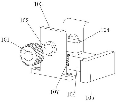
[0039] On the basis of Example 1, as Figure 4-7 As shown, a processing device for electric tool sawtooth, including a No. 1 stabilizing plate 5, the four corners of the lower end of the No. 1 stabilizing plate 5 are fixedly connected with a No. 1 support column 1, and the front right part of the No. 1 stabilizing plate 5 is fixedly connected with a control box. 2. There is a groove 17 in the middle of the upper end of the No. 1 stable plate 5, and a moving plate 6 is arranged directly above the No. 1 stable plate 5. The four corners of the upper end of the moving plate 6 are all socketed with a No. 1 limit rod 16, four No. 1 The lower part of the outer surface of the limit rod 16 is sleeved with a No. 1 limit block 18, the lower ends of the four No. 1 limit rods 16 are fixedly connected with a No. 1 stable block 4, and the middle part of the upper end of the moving plate 6 is fixedly connected with a clamping device 19 , the lower front part of the moving plate 6 and the lowe...


PUM


Abstract

The invention discloses a machining device for electric tool sawteeth. The machining device comprises a first stabilizing plate, and first supporting columns are fixedly connected to the four corners of the lower end of the first stabilizing plate. A clamping device is fixedly connected to the middle of the upper end of a moving plate, and a moving device is jointly and fixedly connected to the front portion and the rear portion of the lower end of the moving plate. A second stabilizing plate is fixedly connected to the left portion of the upper end of the first stabilizing plate, a pushing device is fixedly connected to the front portion of the upper end of the second stabilizing plate, a turnover device is movably connected to the upper end of the pushing device, a grinding machine is fixedly connected to the left end of the turnover device, and a lifting device is fixedly connected to the rear portion of the upper end of the first stabilizing plate. A sliding device is slidably connected to the upper end of the lifting device, and a third stabilizing plate is fixedly connected to the front portion of the upper end of the lifting device. The machining device for the electric tool sawteeth can be adapted to polishing of sawtooth products with different thicknesses, the using range is widened, and the equipment utilization rate is increased.

Description

technical field [0001] The invention relates to the technical field of electric tool processing, in particular to a processing device for electric tool sawtooth. Background technique [0002] The chainsaw, also known as the "power saw", was invented by the German Andreas Steele in 1926, which greatly saved the time and manpower spent on cutting materials. The chainsaw uses electricity as power for Cutting tools for cutting wood, stone, steel, etc. have sharp teeth on the edge, which are divided into fixed and portable. The saw blade is generally made of tool steel, and there are many types such as round, strip and chain. 1. Currently sawtooth Punching the blank center hole is an indispensable and important link in the sawtooth processing, but the existing gear center hole punching equipment still has some deficiencies in use. The sawtooth is not fixed firmly during the punching process, which affects the sawtooth punching. 2. The existing sawtooth grinding is difficult to o...

Claims


Application Information

Patent Timeline
Patent Type & Authority Applications(China)
IPC IPC(8): B23D65/00
CPCB23D65/00
Inventor 黄军梅张芯语陈建龙
Owner 东莞市鸿安自动化科技有限公司
Why Eureka
Try Eureka