Laser-assisted friction stir additive welding tool and device

A friction stir and laser-assisted technology, which is applied in the direction of additive processing, manufacturing tools, welding equipment, etc., can solve the problem of not being able to protect the tool handle well from heat, achieve high-speed friction stir additive manufacturing, reduce system redundancy, reduce The effect of the control logic

Active Publication Date: 2021-06-22
苏州万智新能源科技有限公司
View PDF13 Cites 1 Cited by
  • Summary
  • Abstract
  • Description
  • Claims
  • Application Information

AI Technical Summary

Problems solved by technology

[0004] Therefore, the technical problem to be solved by the present invention is to overcome the defect that the tool handle cannot be well protected from heat in the process of laser auxiliary heating in the prior art, so as to provide a laser-assisted friction stir additive welding tool and device

Method used


Image

  • Laser-assisted friction stir additive welding tool and device
  • Laser-assisted friction stir additive welding tool and device
  • Laser-assisted friction stir additive welding tool and device

Examples


Embodiment 1

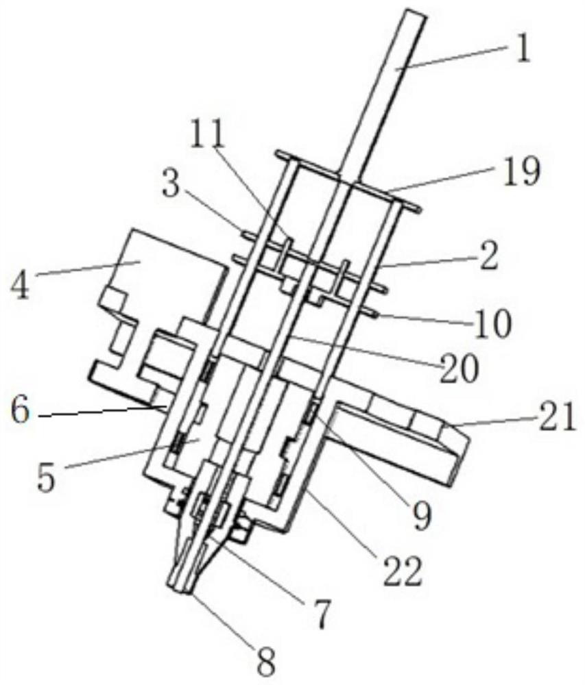
[0035] like Figure 1-4 As shown, this embodiment provides a laser-assisted friction stir additive welding tool, including,

[0036] The handle 7, the side wall of the handle 7 is separated from the laser channel 18, and the side wall of the handle 7 between two adjacent laser channels 8 is a frame structure 23;

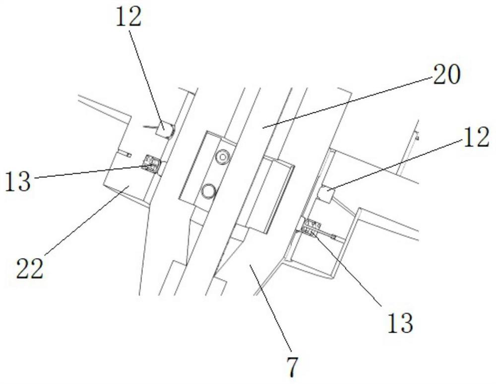
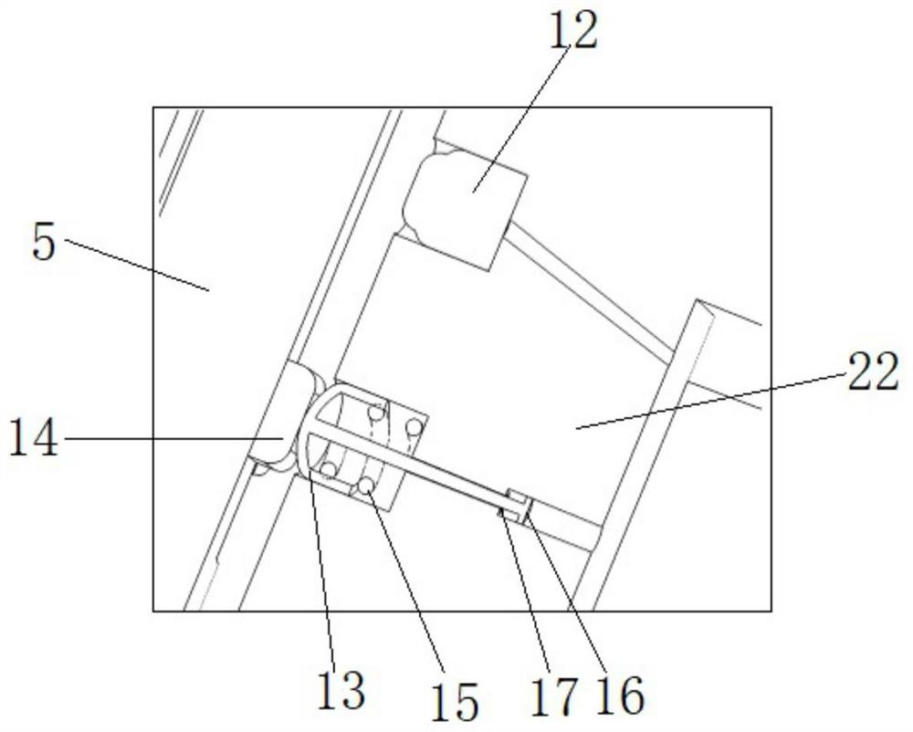
[0037] Housing 22, which has a cavity suitable for passing through the knife handle 7; the knife handle 7 is arranged in the housing 22 in a manner of clearance fit with the housing; the housing 22 has Laser head 12 and push switch, described push switch is electrically connected with described laser head 12; Wherein, described knife handle 7 is adapted to be rotated relative to described housing 22 under the drive of main shaft 5, during rotation, all A part of the frame structure 23 is adapted to abut against the push switch, thereby closing the laser head 12; when the frame structure 23 breaks away from the push switch, the laser head 12 emits laser light, thereb...

Embodiment 2

[0046] like figure 1 As shown, this embodiment also provides a laser-assisted friction stir additive welding device, which adopts the laser-assisted friction stir additive welding tool described in Embodiment 1, and further includes a base 21, the base 21 and the shell The body 22 is connected; the side wall of the housing 22 is provided with a transmission hole, and the base outside the housing is provided with a motor 4, and the driving belt of the motor 4 is transmitted through the transmission hole and the main shaft 4 of the welding tool. connection, specifically, the drive belt can be selected as a belt 6, and the motor 4 drives the main shaft 5 to rotate through the belt 6 to provide power for friction stir welding.

[0047] Optionally, the above-mentioned laser-assisted friction stir additive welding device also includes an additive conveying structure, which includes a guide bracket, and the guide bracket includes an upper plate 19 and a linear drive structure 1 fixed...


PUM


Abstract

The invention relates to the technical field of friction stir welding, in particular to a laser-assisted friction stir additive welding tool. A laser head and a push switch are arranged in a shell of the tool, and the push switch is electrically connected with the laser head; laser channels are formed in the side wall of a cutter handle at intervals, and the side wall of the cutter handle between every two adjacent laser channels is of a frame structure; in the rotating process, one part of a frame body structure is suitable for abutting against the pressing switch, so that the laser head is closed; and when the frame body structure is separated from the pressing switch, the laser head emits laser, so that auxiliary heating is carried out on the additive in the cutter handle through the laser channels. The tool adopts a full-mechanical structure, a laser can accurately heat a material and rapidly heat the material, high-speed friction stir additive manufacturing can be achieved, the defect of mistakenly heating the cutter handle caused by step loss of a motor system is avoided, the control logic of a control system is reduced, and system redundancy is reduced.

Description

technical field [0001] The invention relates to the technical field of friction stir welding, in particular to a laser-assisted friction stir additive welding tool and device. Background technique [0002] As a new solid phase additive technology, friction stir additive manufacturing has the advantages of low forming temperature and good properties of formed materials. However, in the process of adding materials, in order to satisfy the plasticization of the material by sufficient heat, extremely high speed and pressure are required. This will place great demands on the performance of the equipment. During friction stir additive manufacturing, the material needs a lot of temperature to plasticize. However, pure frictional heat generation will cause insufficient plasticization of the material, so auxiliary heat additive manufacturing is required. The laser acts as a good heat source to quickly heat the material to the desired temperature. However, the laser is a kind of c...

Claims


Application Information

Patent Timeline
Patent Type & Authority Applications(China)
IPC IPC(8): B23K20/12B23K20/26B33Y30/00B33Y40/00
CPCB23K20/1215B23K20/1245B23K20/26B33Y30/00B33Y40/00Y02P10/25
Inventor 万龙温琦黄体方
Owner 苏州万智新能源科技有限公司
Why Eureka
Try Eureka