
Large oil cylinder assembling device

A technology for assembling equipment and oil cylinders, used in metal processing equipment, metal processing, manufacturing tools, etc., can solve the problems of low installation efficiency and slow moving speed of end caps, and achieve fast and sensitive length control, easy processing, and shortened horizontal operation. effect of space

Inactive Publication Date: 2021-06-22
CHONGQING JIANGLU LASER TECH
View PDF10 Cites 1 Cited by
  • Summary
  • Abstract
  • Description
  • Claims
  • Application Information

AI Technical Summary

Problems solved by technology

[0005] The present invention intends to provide a large-scale oil cylinder assembly equipment to solve the problem that in the original screw-type hydraulic cylinder processing device, the moving speed of the tooling unit driven by the screw is slow, and the installation efficiency of the end cover on the cylinder body is relatively low. low problem

Method used


Image

  • Large oil cylinder assembling device
  • Large oil cylinder assembling device
  • Large oil cylinder assembling device

Examples


Embodiment Construction

[0031] Further detailed explanation through specific implementation mode below:

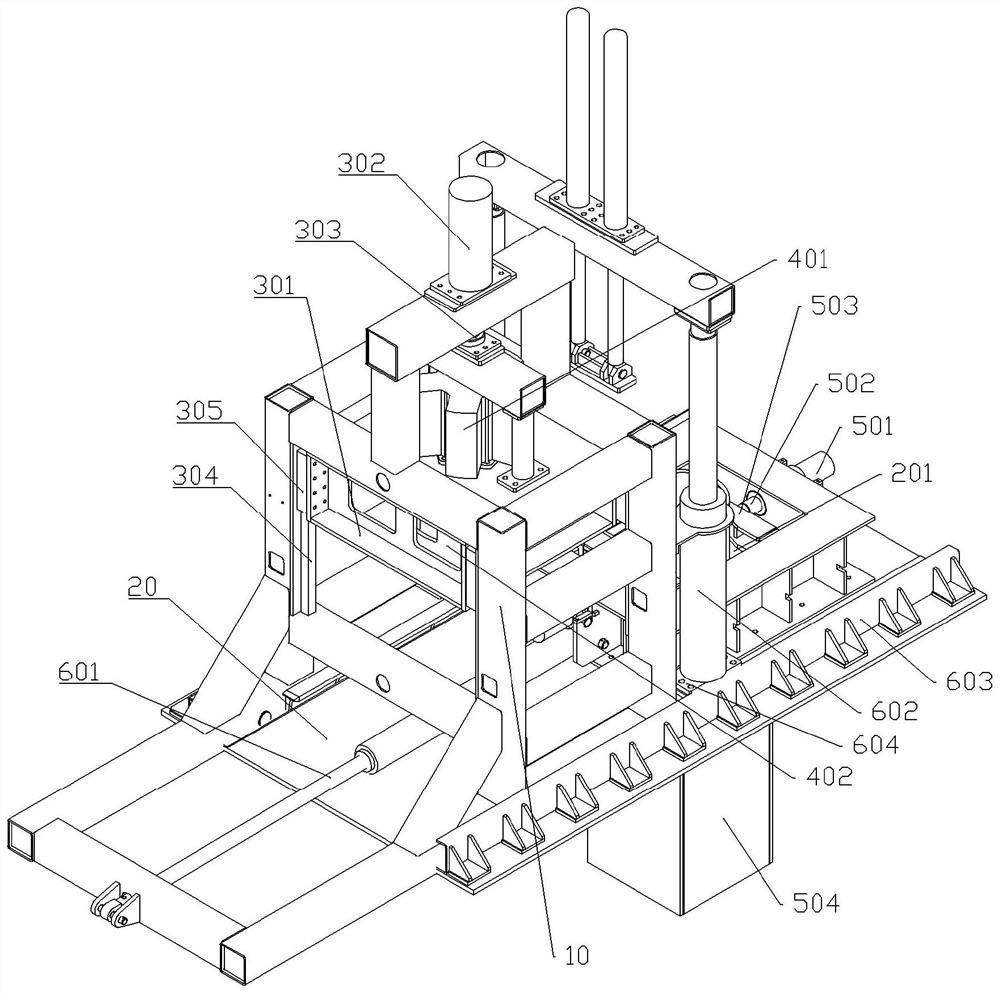
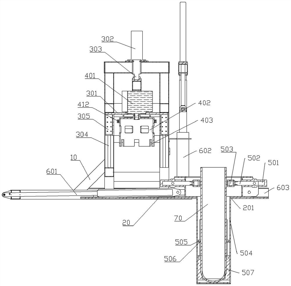
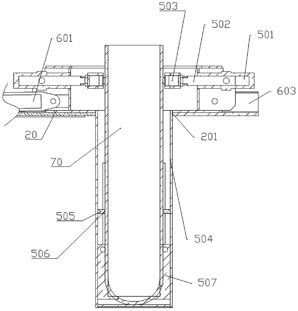
[0032] The reference signs in the drawings of the description include: frame 10, processing table 20, installation hole 201, lifting group frame 301, lifting cylinder 302, second telescopic rod 303, second guide rail 304, second slider 305, first Hydraulic motor 401, swivel head 402, card slot 403, cylinder removal telescopic rod 405, support block 406, second hydraulic motor 407, tight groove 408, upper support block 409, lower support block 410, fixed sleeve 411, ratchet 412, Worktable oil cylinder 501, clamping piston rod 502, limit block 503, fixed cylinder 504, mounting plate 505, through hole 506, support frame 507, first telescopic rod 601, pressing oil cylinder 602, first slide rail 603, second A slider 604 and the housing 70.

[0033] The embodiment is basically as attached figure 1 , attached figure 2 , attached image 3 And attached Figure 4Shown: a large-scale oil cylinder asse...


PUM


Abstract

The invention relates to the field of machining, and particularly discloses a large oil cylinder assembling device. The large oil cylinder assembling device comprises a rack, a machining table, a tool unit capable of clamping an end cover and driving the end cover to rotate, a first moving unit driving the rack to horizontally move and a second moving unit driving the tool unit to vertically move; the tool unit is arranged on the rack; the machining table is provided with an installing hole for a shell to be vertically arranged; the first moving unit comprises a horizontally-arranged first hydraulic telescopic rod, one end of the first hydraulic telescopic rod is connected with the machining table, and the other end of the first hydraulic telescopic rod is connected with the rack; and the second moving unit comprises a vertically-arranged second hydraulic telescopic rod, the upper end of the second hydraulic telescopic rod is connected with the rack, the lower end of the second hydraulic telescopic rod is connected with the tool unit, and the tool unit can right face the installing hole. According to the scheme, length control over the first hydraulic telescopic rod and the second hydraulic telescopic rod is fast and sensitive, the tool unit can be fast controlled to move, and fast installing of the end cover is achieved.

Description

technical field [0001] The invention belongs to the field of mechanical processing, and in particular relates to a large oil cylinder assembly equipment. Background technique [0002] Oil cylinders applied to large-scale equipment have the characteristics of heavy weight and large length. The height of common large-scale oil cylinders is about 1.5m, and when the oil cylinders are assembled vertically, the shell, cylinder body, inner cylinder and end cover of the oil cylinder This also requires a higher processing tube space. [0003] In the prior art, when assembling the shell, cylinder body and end cover of the oil cylinder, the screw is generally used to drive the tooling mechanism to install the end cover. Correspondingly, it is necessary to set up an operating space 2m deep and 4m long on the ground, so that the tooling mechanism It can slide left and right and vertically in the operating space to realize the movement of the workpiece and the assembly and compression of...

Claims


Application Information

Patent Timeline
Patent Type & Authority Applications(China)
IPC IPC(8): B23P19/04
CPCB23P19/04
Inventor 彭学江汤甜周翔
Owner CHONGQING JIANGLU LASER TECH
Learn More