
Section steel rim and wheel

A technology of wheel rim and section steel, which is applied to wheels, rims, spoked wheels, etc., can solve problems such as failure to ensure mutual restraint between wheel and tire assemblies, failure to meet the needs of heavy-load trucks, vehicle safety problems, etc., to improve convenience. , Reduce the failure rate and production cost, the effect of reducing weight

Pending Publication Date: 2021-06-22
兴民力驰有限责任公司
View PDF0 Cites 0 Cited by
  • Summary
  • Abstract
  • Description
  • Claims
  • Application Information

AI Technical Summary

Problems solved by technology

However, due to the limitation of the strength of the inner tube, the air pressure it carries is limited. When the air pressure is too high, the inner tire will burst and cause serious safety problems for the vehicle; if the air pressure is too low, the mutual restraint between the wheel and tire assemblies cannot be guaranteed, and it will also cause the outer tire to deform. , escape and other safety issues
At the same time, because the inner-tyred wheel also includes metal valves, metal gaskets and other structures, the inner-tyred wheel has disadvantages such as heavy weight, high energy consumption, and not being environmentally friendly.
[0003] In contrast, tubeless wheels have the advantages of light weight, safety, energy saving, and environmental protection, but they have low load capacity and short life, which cannot meet the needs of large-load trucks and automobiles, such as engineering vehicles, mining vehicles, dump trucks, etc.

Method used


Image

  • Section steel rim and wheel
  • Section steel rim and wheel
  • Section steel rim and wheel

Examples


Embodiment Construction

[0046] The principles and features of the present invention are described below in conjunction with the accompanying drawings, and the examples given are only used to explain the present invention, and are not intended to limit the scope of the present invention.

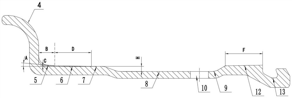
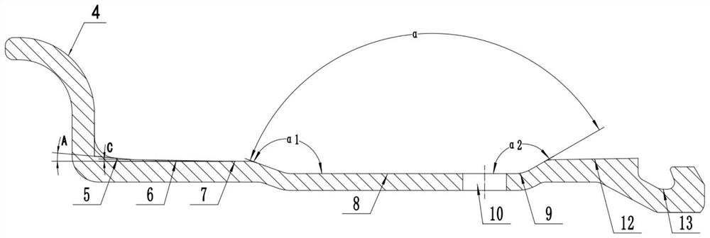
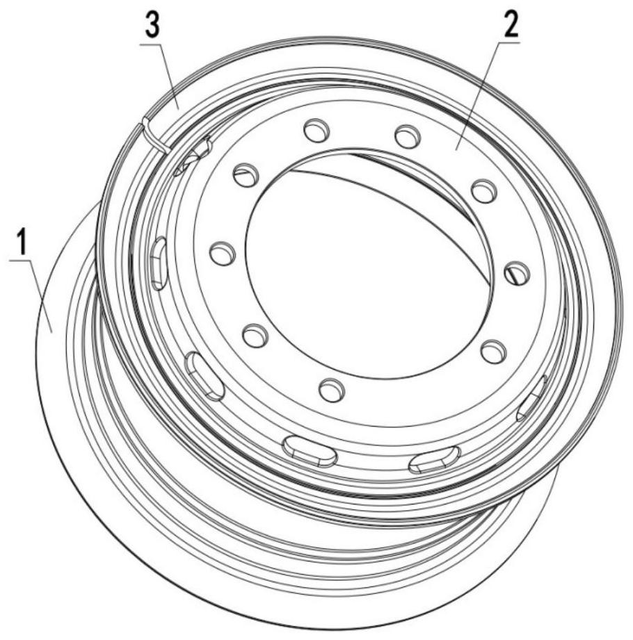
[0047] Such as Figure 1 to Figure 5As shown, a steel wheel rim includes a rim main body 1, one side of the rim main body 1 is provided with a fixed rim 4, and the other side is provided with a locking ring groove 13, and the connection between the fixed rim 4 and the locking ring groove 13 is The rim main body 1 in between is provided with a bottom groove 8, and the rim main body 1 between the fixed rim 4 and the bottom groove 8 is provided with a first bead seat 5 and a second bead seat 6, and the lock ring groove The third bead seat 12 is provided on the rim body 1 between 13 and the bottom groove 8, and the angle A between the first bead seat 5 and the axis of the rim body 1 is larger than that between the secon...


PUM

PropertyMeasurementUnit
Angle aaaaaaaaaaa
Angleaaaaaaaaaa
Widthaaaaaaaaaa

Abstract

The invention relates to a profile steel rim and a wheel, and the profile steel rim comprises a rim body; a fixed wheel flange is arranged on one side of the rim body, a locking ring groove is formed in the other side of the rim body, a bottom groove is formed in the portion, between the fixed wheel flange and the locking ring groove, of the rim body, and a first bead seat and a second bead seat are arranged on the portion, between the fixed wheel flange and the bottom groove, of the rim body. A third bead seat is arranged on the rim body between the locking ring groove and the bottom groove, the included angle A between the first bead seat and the axis of the rim body is larger than or equal to the included angle C between the second bead seat and the axis of the rim body, and the included angle G is formed by the third bead seat and the axis of the rim body. The first bead seat and the third bead seat are arranged, and the included angle is formed between the two bead seats and the axis of the rim main body, that is, an inclined plane is formed on the rim main body, so that the rim main body is in full contact with a mounted tire, air leakage is avoided, and the sealing performance is improved; and the second bead seat has a guiding effect on the mounted tire, so that the tire mounting convenience is improved.

Description

technical field [0001] The invention relates to the technical field of auto parts manufacturing, in particular to a steel wheel rim and a wheel. Background technique [0002] At present, automobile wheels are mainly divided into shaped steel wheels (also known as inner tube wheels) and tubeless wheels according to the type of tires used. Wheels with inner tubes have the advantage of high load capacity, but because wheels with inner tubes mainly include four structural materials such as wheels, inner tubes, inner tube pads and outer tires, when the inner tube reaches a suitable air pressure and expands, friction will be generated between the four structural materials. thereby constraining each other. However, due to the limitation of the strength of the inner tube, the air pressure it carries is limited. When the air pressure is too high, the inner tire will burst and cause serious safety problems for the vehicle; if the air pressure is too low, the mutual restraint between ...

Claims


Application Information

Patent Timeline
IPC IPC(8): B60B3/10B60B21/02B60C29/02
CPCB60B3/10B60B21/02B60C29/02
Inventor 高赫男王杰功于景超谢晖
Owner 兴民力驰有限责任公司
Learn More