
Light source module and ceiling lamp

A technology of light source module and light source board, applied in the field of LED lighting, can solve the problems of unreasonable structure of light source module, dark spots of ceiling lamps, affecting user experience and so on.

Pending Publication Date: 2021-06-22
FOSHAN ELECTRICAL & LIGHTING
View PDF0 Cites 1 Cited by
  • Summary
  • Abstract
  • Description
  • Claims
  • Application Information

AI Technical Summary

Problems solved by technology

[0003] However, due to the unreasonable structure of the existing light source module, such as the power box protruding from the surface of the light source, dark spots will appear in the replaced ceiling lamp
Especially with the emergence of intelligent lamps, various functional modules are added to the inside of the power box, resulting in an increase in the volume of the power box, and the phenomenon of dark spots is more obvious, which affects the user experience
At the same time, when the light source module is installed on the original ceiling lamp, it is inconvenient to install, and it is often necessary to remove the whole ceiling lamp before replacing it, which increases the difficulty of replacement

Method used


Image

  • Light source module and ceiling lamp
  • Light source module and ceiling lamp
  • Light source module and ceiling lamp

Examples


Embodiment 1

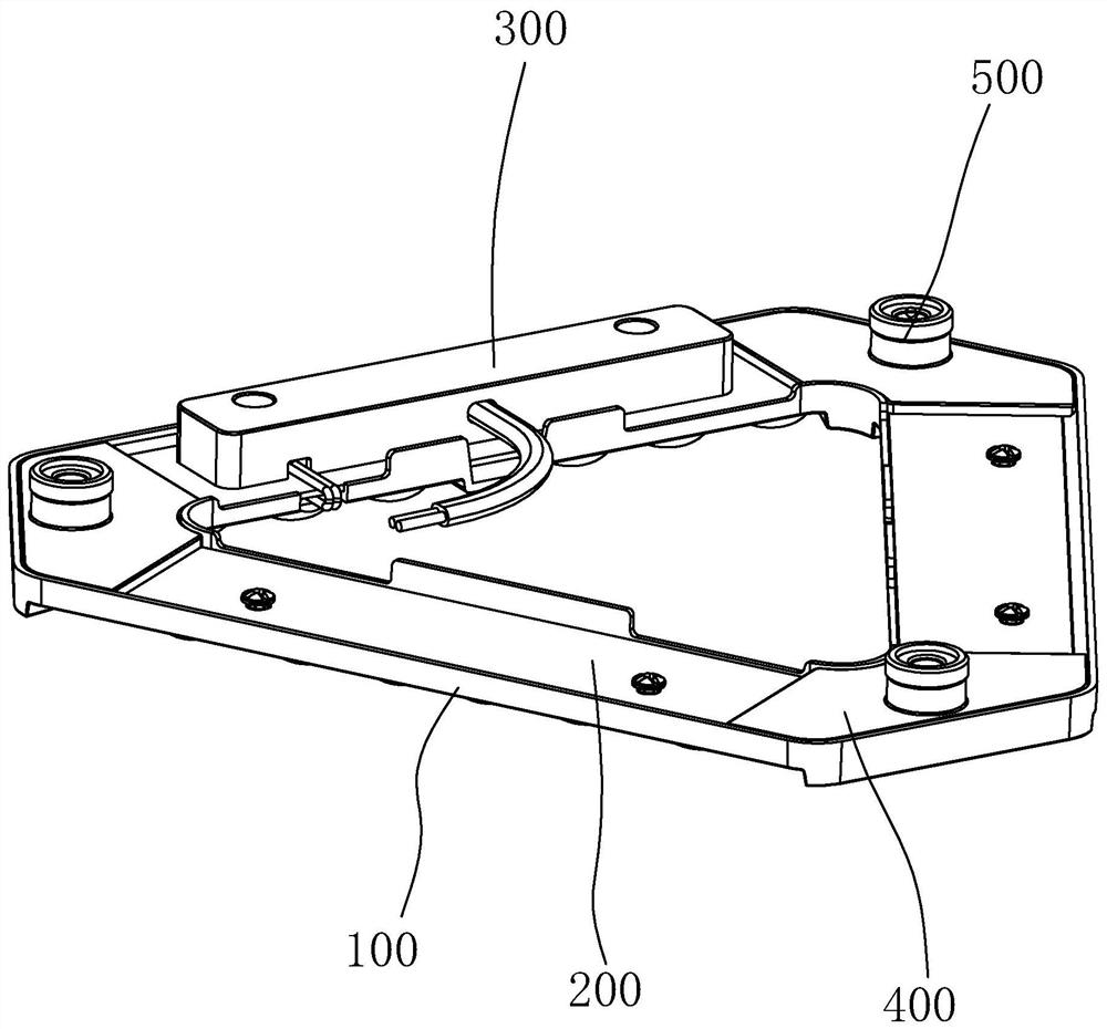
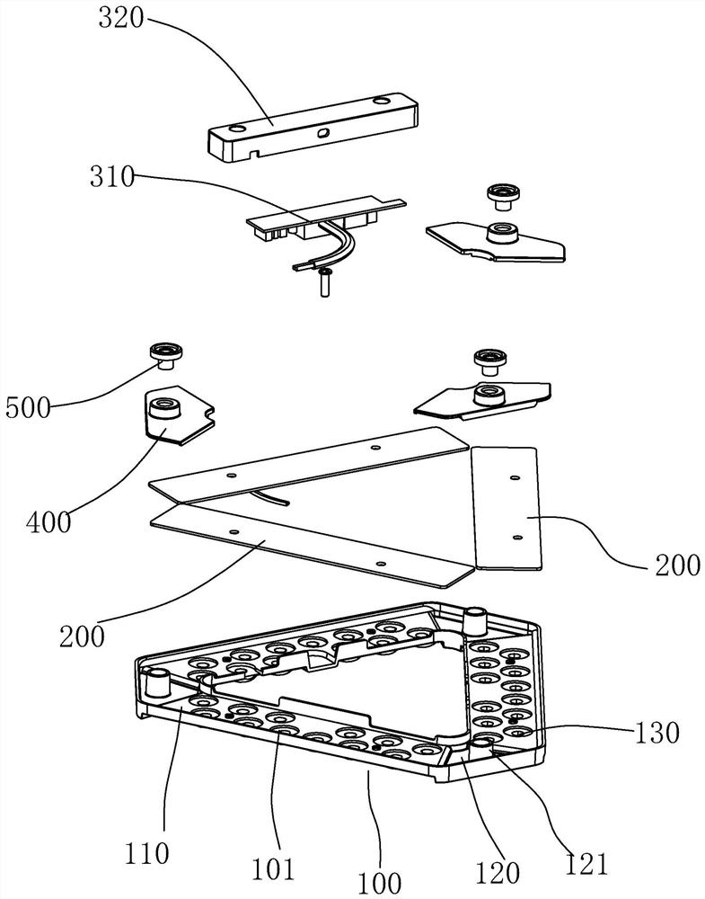
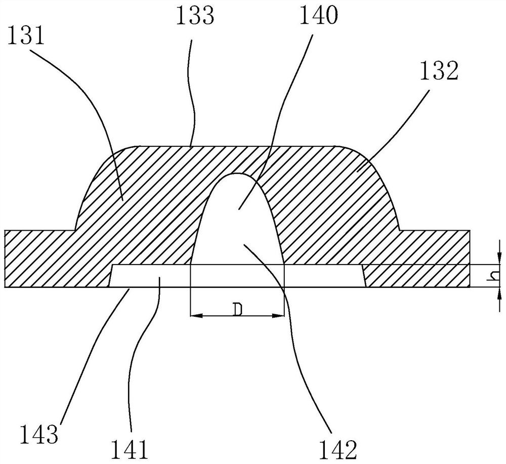
[0030] Embodiment one, with reference to Figure 1 ~ Figure 3 , a light source module, including a lens 100, a light source board 200, a power supply assembly 300, and a magnet seat 400, the lens 100 is roughly triangular in shape, the middle of the lens 100 is hollow, and the lens 100 includes a light source installation cavity 110 and Magnet installation chamber 120, the lens 100 is provided with ribs 101 around the light source installation chamber 110, there are three light source installation chambers 110 and three magnet installation chambers 120, three light source boards 200, three light source boards The board 200 is respectively installed in three light source installation cavities 110, the front of the light source board 200 is provided with a plurality of lamp beads, and the light source installation chamber 110 is provided with a plurality of lens units 130, and the lamp beads and The lens units 130 correspond one-to-one; there are three magnet mounts 400, and the...

Embodiment 2

[0039] Embodiment two, see Figure 5 , Figure 6 , a light source module. The light source module of this embodiment has a similar lens unit 130 structure to that of Embodiment 1, but the shape of lens 100 is different from that of Embodiment 1. In Embodiment 2, the lens 100 as a whole is Square, the middle of the lens 100 is also hollowed out, and the back of the lens 100 is provided with a ring-shaped light source plate 200 . In this embodiment, the back of the lens 100 does not need to be provided with a magnet seat installation cavity, the magnet seat 400 is directly bonded to the back of the light source board 200 , and the power supply assembly 300 is also directly bonded to the back of the light source board 200 .

[0040] Different from Embodiment 1, the snap connection between the light source board 200 and the lens 100 is completed through the clamping post 150. Specifically, the light source board 200 is provided with a clamping hole 210, and the clamping post 150 ...


PUM

PropertyMeasurementUnit
Beam angleaaaaaaaaaa

Abstract

The invention discloses a light source module. The light source module comprises a lens, a light source plate and a power source assembly; the lens is arranged on the front face of the light source plate; the power source assembly is arranged on the back face of the light source plate; and the light emitting angle of the lens is larger than 160 degrees. According to the light source module of the invention, the power source assembly is arranged on the back surface of the light source plate, so that the influence of the power source assembly on light emitting can be effectively avoided, the purpose of improving the light emittingeffect is achieved, and dark spots are avoided; and meanwhile, the power source assembly is arranged on the back face of the light source plate, the front face of the light source plate can be closer to a mask of the ceiling lamp during use, and the light emitting effect of the ceiling lamp can be affected, so that the structure of the lens is improved at the same time, the lens has a larger light emitting angle,an adverse effect which appears after the light source plate is close to the mask is eliminated, and the light emitting effect of the ceiling lamp is improved.

Description

technical field [0001] The invention relates to the field of LED lighting, in particular to a light source module and a ceiling lamp. Background technique [0002] Ceiling lamp is a kind of light fixture. Because the top of the light fixture is relatively flat, the bottom of the light fixture is completely attached to the roof when installed, so it is called ceiling light. The light sources of traditional ceiling lamps include ordinary white light bulbs, fluorescent lamps, high-intensity gas discharge lamps, and tungsten-halogen lamps. With the development of science and technology, LEDs have been widely used as light sources in new lamps. However, due to historical reasons, there are still many old lamps that still use traditional light sources. In order to improve the lighting effect of the environment, in recent years, LED light source modules have been used to replace the old light source, and it has gradually become a cost-effective. Tall old lamp renovation scheme. ...

Claims


Application Information

Patent Timeline
IPC IPC(8): F21S2/00F21V5/04F21V23/02F21V19/00F21V17/12F21Y115/10
CPCF21S2/005F21V5/04F21V23/023F21V19/001F21V19/003F21V17/12F21Y2115/10Y02B20/30
Inventor 胡川魏彬朱奕光邱华敏钟观平蔡泽锋
Owner FOSHAN ELECTRICAL & LIGHTING
Learn More