
Industrial waste combustion treatment device with waste heat utilization function

A technology for industrial waste and treatment equipment, which is applied in the direction of combustion method, combustion type, transportation and packaging, etc., can solve the problems of waste of resources, impact on incineration efficiency, lack of recovery of incineration heat energy, etc., to facilitate recycling conversion, avoid waste of resources, Avoid the effect of spreading out

Inactive Publication Date: 2021-06-22
杨雄
View PDF0 Cites 0 Cited by
  • Summary
  • Abstract
  • Description
  • Claims
  • Application Information

AI Technical Summary

Problems solved by technology

[0008] The object of the present invention is to provide an industrial waste incineration treatment device with the function of utilizing waste heat to solve the problem that the existing incineration device for incineration of industrial waste proposed in the above background technology lacks the recovery of heat energy generated by incineration, resulting in waste of resources. And when waste is incinerated, due to the presence of wet substances in the waste, it is difficult to incinerate industrial waste, which affects the incineration efficiency, and the smoke generated during waste incineration is easy to block the exhaust pipe and the filter element inside the exhaust pipe, affecting the working stability of the incineration device. question

Method used


Image

  • Industrial waste combustion treatment device with waste heat utilization function
  • Industrial waste combustion treatment device with waste heat utilization function
  • Industrial waste combustion treatment device with waste heat utilization function

Examples


Embodiment Construction

[0034] The following will clearly and completely describe the technical solutions in the embodiments of the present invention with reference to the accompanying drawings in the embodiments of the present invention. Obviously, the described embodiments are only some, not all, embodiments of the present invention. Based on the embodiments of the present invention, all other embodiments obtained by persons of ordinary skill in the art without making creative efforts belong to the protection scope of the present invention.

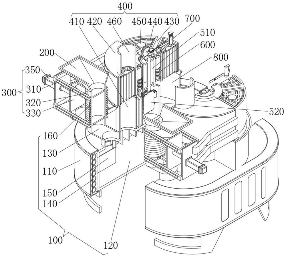
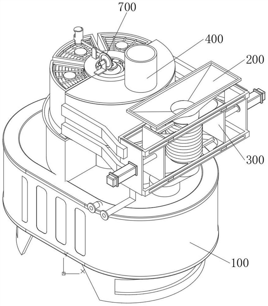
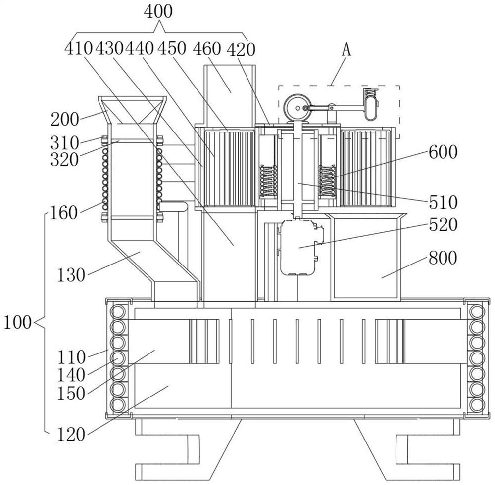
[0035] see Figure 1-9 , an embodiment provided by the present invention: an industrial waste combustion treatment device with the function of utilizing waste heat, including an incinerator main body 100, the incinerator main body 100 includes an incineration chamber shell 110, and the interior of the incineration chamber shell 110 is fixedly installed with The incineration chamber main body 120, the top of the incineration chamber main body 120 is fixedly con...


PUM


Abstract

The invention relates to the technical field of industrial waste treatment equipment, in particular to an industrial waste combustion treatment device with a waste heat utilization function. The device comprises an incineration machine main body, wherein the incineration machine main body comprises an incineration chamber shell, an incineration chamber main body is fixedly mounted in the incineration chamber shell, the top of the incineration chamber main body fixedly communicates with a feeding pipe, a heating pipe is fixedly installed between the incineration chamber shell and the incineration chamber main body, and the heating pipe is wound around and fixed to the outer wall of the incineration chamber main body. According to the device, the heating pipe wraps the outer side of the incineration chamber main body, a heat conduction metal sheet is inserted into the incineration chamber main body, one end of the outer side of the heat conduction metal sheet is connected with the heating pipe, through guiding and transferring of heat energy by the heat conduction metal sheet, purified water injected into the heating pipe is heated to form water vapor, energy conversion and collection are facilitated, heat generated during waste incineration of the device can be recycled, and resource waste can be avoided conveniently.

Description

technical field [0001] The invention relates to the technical field of industrial waste treatment equipment, in particular to an industrial waste combustion treatment device with the function of utilizing waste heat. Background technique [0002] With the development and progress of science and technology, people's skills in industrial manufacturing are becoming more and more mature. In today's production and life, the field of industrial manufacturing is also gradually growing, providing important material support for people's lives. In the existing technology, industrial manufacturing During the process, due to the change of the form of the material, a certain amount of industrial waste is usually produced. In order to reduce the harmful impact of industrial waste on people's living environment, the industrial waste is usually sorted and sorted after the industrial waste is produced. The wastes with recycling value are recycled, and the wastes that can be burned without ot...

Claims


Application Information

Patent Timeline
Patent Type & Authority Applications(China)
IPC IPC(8): F23G7/00F23G5/04F23G5/10F23G5/46F23J15/02B01D46/00
CPCF23G7/00F23G5/10F23G5/46F23G5/04F23J15/025B01D46/76
Inventor 杨雄
Owner 杨雄
Learn More