Two-dimensional phased array microwave front-end calibration network and method

A calibration method and phased array technology, applied in radio transmission systems, electrical components, transmission systems, etc., can solve problems such as complex circuits and difficult layouts, and achieve the effect of simple circuits, reduced design difficulty, and simple circuits

Active Publication Date: 2021-06-22
CNGC INST NO 206 OF CHINA ARMS IND GRP
View PDF11 Cites 2 Cited by
  • Summary
  • Abstract
  • Description
  • Claims
  • Application Information

AI Technical Summary

Problems solved by technology

[0007] In order to solve the disadvantages of the prior art, such as limited test site for external calibration and internal calibration, circuit complexity and difficult layout, the present invention proposes a two-dimensional phase Calibration network and method for controlled array microwave front-end

Method used


Image

  • Two-dimensional phased array microwave front-end calibration network and method
  • Two-dimensional phased array microwave front-end calibration network and method
  • Two-dimensional phased array microwave front-end calibration network and method

Examples


Embodiment Construction

[0032] Now in conjunction with embodiment, accompanying drawing, the present invention will be further described:

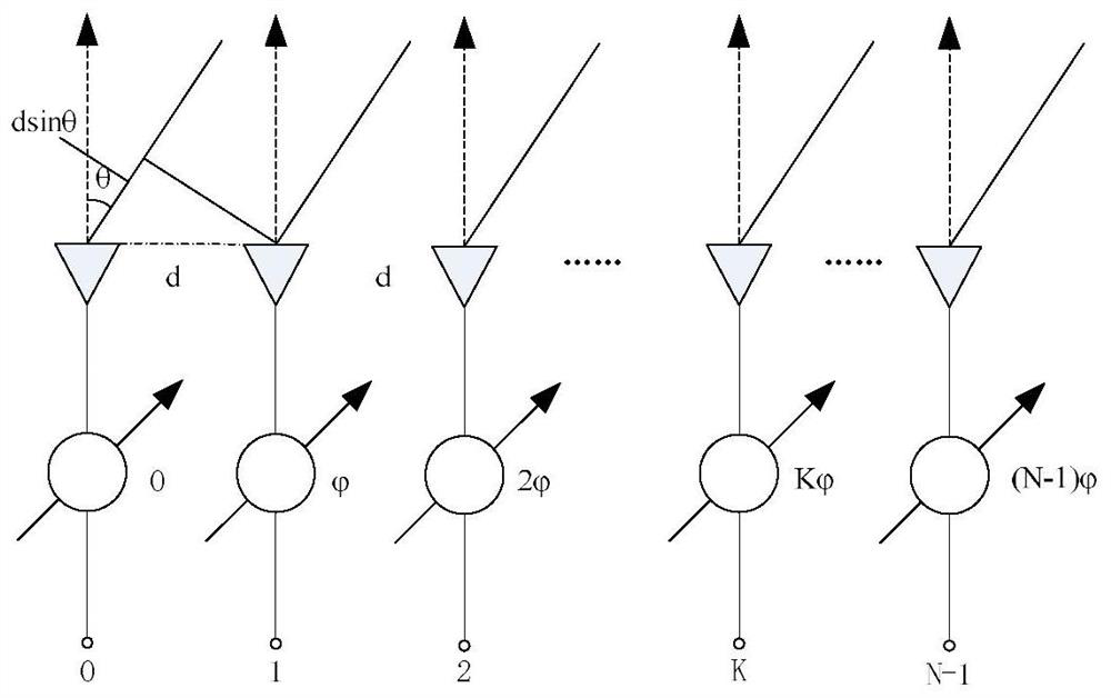
[0033] Phased array antenna beam scanning is realized by controlling the phase shifter phase of each radiating element to form a scanning equiphase plane, and changing the excitation phase of each antenna element by controlling the state of the phase shifter to realize phase scanning. Taking N-element linear array as an example, d is the spacing between antenna elements, is the phase difference between channels, and 2πdsinθ / λ is the phase difference of the radiation field of adjacent antenna elements caused by the wave path difference. The resultant vector sum of the field strength of each array element at a point in the far-field area in the θ direction is:

[0034]

[0035] Change value, the beam pointing angle θ can be changed to form a beam scan. When the system is working, the amplitude and phase of the sending and receiving signals are weighted for ...


PUM


Abstract

The invention relates to a two-dimensional phased array microwave front-end calibration network and method, and belongs to the field of two-dimensional phased array microwave front-end system design, wherein the calibration network is realized by adopting N linear arrays with N channels, and the first channel of each linear array is connected with a coupler. The calibration process comprises the following steps: independently calibrating the TR assembly, the antenna array and the calibration channel; according to the TR assembly and the antenna array, obtaining an initial control code trimmed in the linear array; verifying and correcting the initial control code in the linear array in combination with near-field testing; performing real-time calibration between the linear arrays to obtain amplitude and phase differences between the linear arrays; and finally, subtracting the sum of the initial code of the calibration channel and the amplitude and phase difference of the real-time calibration from the control code of the near-field test to obtain a final control code. Fixed initial calibration data is adopted in one dimension, and real-time internal calibration is performed in the other dimension, so the complexity of a calibration network is reduced, the calibration efficiency is improved, and the array surface scale can be expanded.

Description

technical field [0001] The invention belongs to the field of two-dimensional phased array microwave front-end system design, specifically a simple, effective, and low-cost calibration network and method, which is mainly used in two-dimensional phased array radar systems to realize the two-dimensional phased array microwave front-end system. Real-time online monitoring, fast speed, high reliability, stable performance and high precision. It is suitable for the two-dimensional phased array microwave system of one-dimensional synthesis and one-dimensional digital beamforming, which is common at present, and has good versatility. Background technique [0002] With the development of modern microwave integration technology, phased array technology is more and more widely used in radar, countermeasures and communication due to its multi-independent beam capability, flexible and rapid control, multi-function, high reliability and conformal application. system. In terms of circuit...

Claims


Application Information

Patent Timeline
Patent Type & Authority Applications(China)
IPC IPC(8): H04B7/0404H04B7/01
CPCH04B7/0404H04B7/01
Inventor 刘俊武华锋李辉杨莉王元源席安安
Owner CNGC INST NO 206 OF CHINA ARMS IND GRP
Why Eureka
Try Eureka