Eureka AIR delivers breakthrough ideas for toughest innovation challenges, trusted by R&D personnel around the world.

Waste lithium battery electrolyte wastewater recovery treatment device

A waste lithium battery and waste water recycling technology, which is applied in the fields of magnetic/electric field water/sewage treatment, water/sewage treatment, neutralized water/sewage treatment, etc., can solve the problems of difficult electrolyte wastewater treatment and environmental pollution, etc.

Active Publication Date: 2021-06-25
YICHUN JINHUI NEW ENERGY MATERIALS
View PDF15 Cites 4 Cited by
  • Summary
  • Abstract
  • Description
  • Claims
  • Application Information

AI Technical Summary

Problems solved by technology

[0004] In order to overcome the shortcomings of electrolyte wastewater that is difficult to handle and pollute the environment in the process of making lithium batteries, the technical problem is to provide a waste lithium battery electrolyte wastewater recovery and treatment device that can automatically recycle and treat electrolyte wastewater, and is simple and safe to operate.

Method used


Image

  • Waste lithium battery electrolyte wastewater recovery treatment device
  • Waste lithium battery electrolyte wastewater recovery treatment device
  • Waste lithium battery electrolyte wastewater recovery treatment device

Examples


Embodiment 1

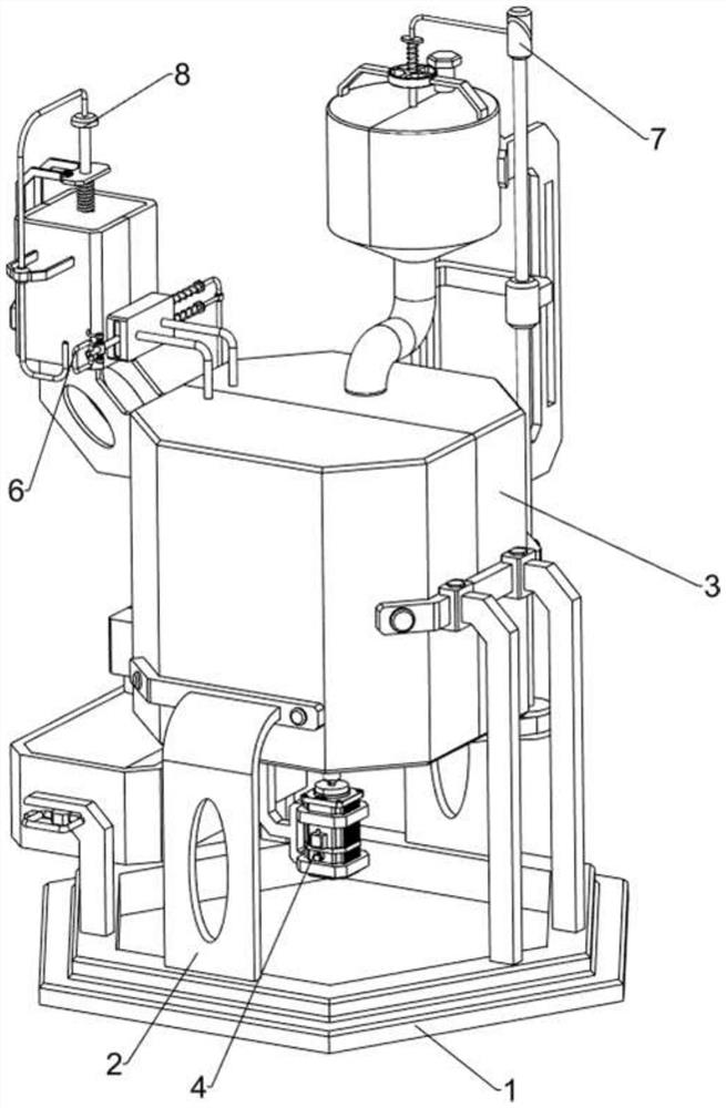
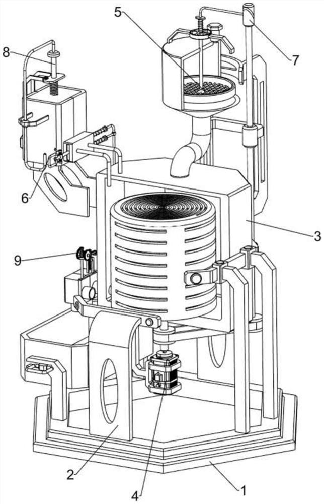
[0070] A waste lithium battery electrolyte wastewater recovery treatment device, such as Figure 1-5 As shown, it includes a base 1, a first pillar 2, a box body 3, a rotating mechanism 4 and a shaking mechanism 5, and the left and right sides of the base 1 are provided with first pillars 2, and a box body 3 is connected between the first pillars 2. , The box body 3 is provided with a rotating mechanism 4, and the right side of the box body 3 is provided with a shaking mechanism 5.

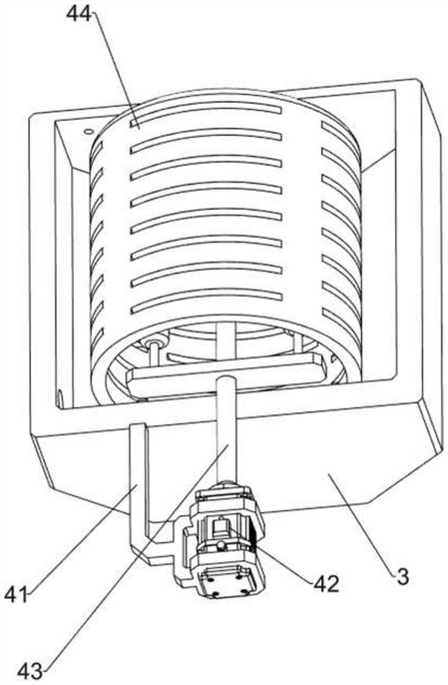
[0071] The rotating mechanism 4 includes a first support 41, a servo motor 42, a first rotating shaft 43, a filter frame 44 and a magnetic soft cloth rod 45. The bottom of the casing 3 is provided with a first support 41, and the first support 41 is provided with a servo motor. 42. The output shaft of the servo motor 42 is connected with the first rotating shaft 43, the filter screen frame 44 is arranged on the first rotating shaft 43, and the magnetic soft cloth rod 45 is arranged at the lower pa...

Embodiment 2

[0075] On the basis of Example 1, such as Figure 6-9 As shown, an acid replenishing mechanism 6 is also included, and the acid replenishing mechanism 6 includes a second pillar 61, a liquid storage tank 62, a pull handle 63, a first baffle 64, a second outlet pipe 65, a second sliding rod 66 and a second Two springs 67, two second pillars 61 are arranged on the rear side of the box body 3, and a liquid storage tank 62 is connected between the tops of the second pillars 61, and the lower side of the front part of the liquid storage tank 62 is slidingly connected with a first baffle plate 64, the second The left side of a baffle plate 64 is provided with a pull handle 63, the upper and lower sides of the right part of the first baffle plate 64 are provided with a second slide bar 66, and a second slide bar 66 is provided between the right side of the second slide bar 66 and the liquid storage tank 62. A spring 67 , and a second water outlet pipe 65 is connected between the fron...


PUM


Abstract

The invention relates to a treatment device, in particular to a waste lithium battery electrolyte wastewater recovery treatment device. The technical problem is to provide a waste lithium battery electrolyte wastewater recovery treatment device which can automatically recover and treat electrolyte wastewater and is simple and safe to operate. According to the technical scheme, the waste lithium battery electrolyte wastewater recycling device comprises a base and first supporting columns arranged on the two sides of the base; a box body connected between the first supporting columns; a rotating mechanism arranged on the box body; and a shaking mechanism arranged on one side of the box body. Through cooperation of an acid supplementing mechanism, the rotating mechanism and the shaking mechanism, wastewater can be screened, and meanwhile, the effect of interval acid supplementing is achieved.

Description

technical field [0001] The invention relates to a treatment device, in particular to a waste lithium battery electrolyte wastewater recycling and treatment device. Background technique [0002] Today, most electronic devices such as smartphones, tablets, wearables, and electric vehicles use rechargeable lithium-ion batteries. However, after two to three years of use, these lithium-ion batteries will degrade in function and efficiency, or even reach the end of their life. Once the electrolyte of waste lithium-ion batteries flows into the soil or is exposed to the environment, there will be great pollution. In addition, in the process of producing lithium batteries, some waste electrolyte wastewater will also be produced. If these electrolyte wastewater Discharged into the environment without treatment will also cause great pollution. [0003] Therefore, how to safely and effectively treat these waste lithium battery electrolytes is of great significance. Now, a waste lithiu...

Claims


Application Information

Patent Timeline
Patent Type & Authority Applications(China)
IPC IPC(8): C02F1/00C02F1/28C02F1/48C02F1/66B01D33/03
CPCC02F1/48C02F1/28C02F1/001C02F1/66B01D33/0353Y02W30/84
Inventor 何业峰
Owner YICHUN JINHUI NEW ENERGY MATERIALS
Why Eureka
Eureka Blog
Learn More