Glass processing device
A processing device and glass technology, applied in lighting and heating equipment, steam/steam condenser, etc., can solve problems such as inability to recycle and reuse water bodies, and achieve improved cooling processing production efficiency, strong operability, and improved stability Effect
- Summary
- Abstract
- Description
- Claims
- Application Information
AI Technical Summary
Problems solved by technology
Method used
Image
Examples
Embodiment 1
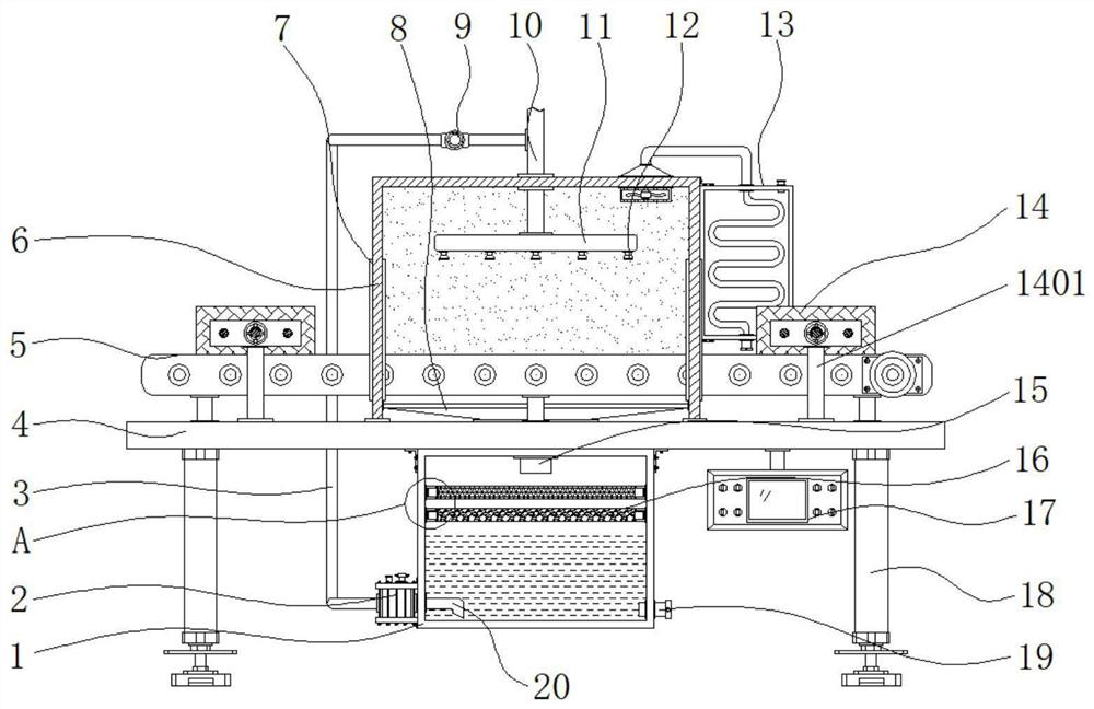
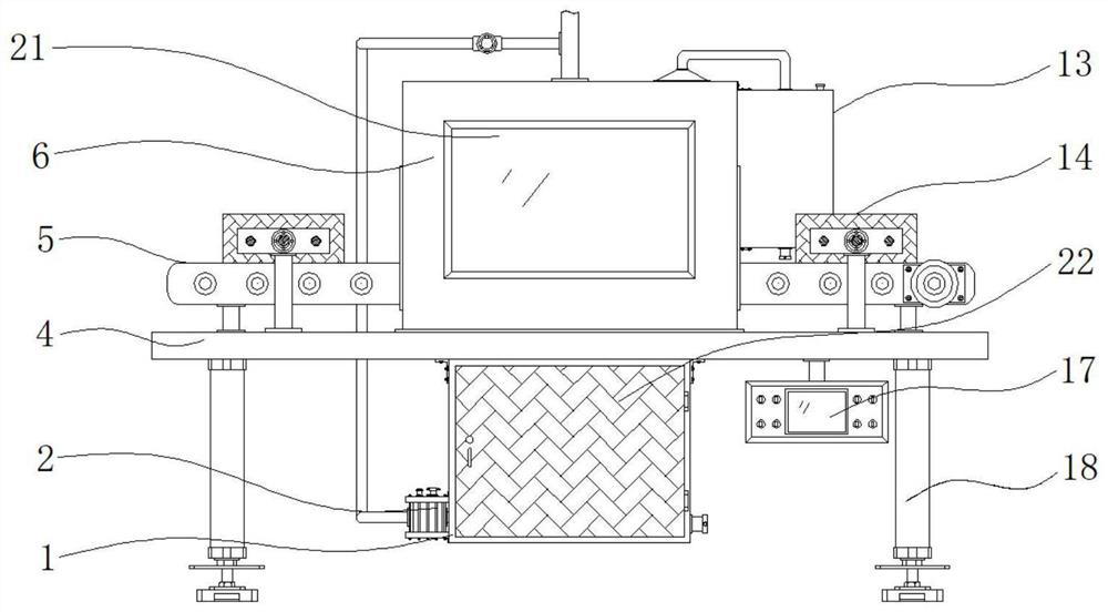
[0035] Example 1: See Figure 1-6 , a glass processing device, comprising a base plate 4, the four corners of the bottom end of the base plate 4 are fixedly connected with supporting columns 18, the middle position of the top end of the base plate 4 is fixedly connected with a frame body 6, and the two sides of the frame body 6 are respectively provided with A reserved groove 7 is fixedly connected to a purification box 1 at the middle position of the bottom end of the bottom plate 4, and the bottom end of one side of the purification box 1 is plugged with a drain port 19, and a conveying mechanism 5 is arranged at the middle position of the top end of the bottom plate 4, and the bottom of the bottom plate 4 One end of one side is fixedly connected with a control panel 17, and the bottom end of the frame body 6 of the bottom plate 4 is fixedly connected with a water collecting bucket 8, and the bottom end of the water collecting bucket 8 is fixedly connected with a downwater pi...
Embodiment 2
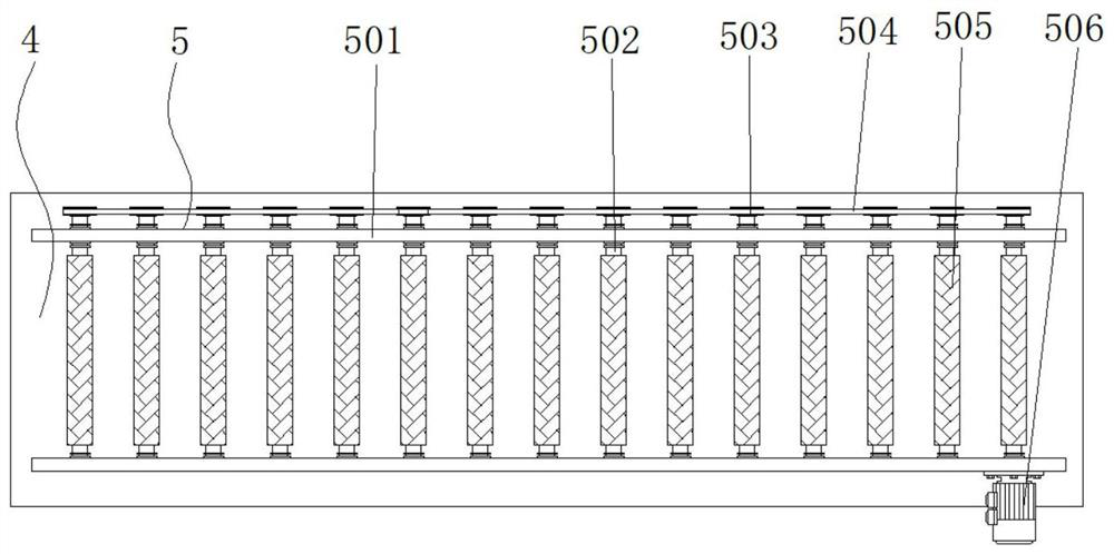
[0038] Embodiment 2: The conveying mechanism 5 is composed of a fixed horizontal plate 501, a rotating shaft 502, a pulley 503, a transmission belt 504, an anti-slip sleeve 505 and a drive motor 506. The fixed horizontal plate 501 is respectively fixedly connected to the two ends of the top of the bottom plate 4, and the fixed horizontal plate 501 There is a rotating shaft 502 evenly and flexibly connected between them, and a drive motor 506 is fixedly connected to one end of the fixed horizontal plate 501. The output end is fixedly connected, the other end of the rotating shaft 502 runs through the other end of the fixed horizontal plate 501 respectively, the other end of the rotating shaft 502 is respectively fixedly connected with a pulley 503, a transmission belt 504 is arranged between the pulleys 503, and the outside of the rotating shaft 502 is fixedly connected with an anti-skid Set 505;
[0039] Fifteen groups of rotating shafts 502 are arranged, and the rotating shaf...
Embodiment 3
[0041] Embodiment 3: Exhaust mechanism 13 is made up of condensing box 1301, exhaust fan 1302, steam guide hood 1303, steam delivery pipe 1304, liquid filling port 1305, condensing pipe 1306, liquid discharge port 1307 and water outlet 1308, condensing box 1301 Fixedly connected to the top of one side of the frame body 6, the inside of the condensation box 1301 is provided with a condensation pipe 1306, and the exhaust fan 1302 is fixedly connected to the top side of the frame body 6, and the model of the exhaust fan 1302 can be XG- 3. The output end of the exhaust fan 1302 is fixedly connected with a steam guide hood 1303, and the top of the steam guide 1303 is fixedly connected with a steam pipe 1304, and the bottom end of the steam pipe 1304 runs through the middle position of the top of the condensation box 1301 and the condensation pipe The top of 1306 is fixedly connected, the top side of the condensation box 1301 is plugged with a liquid filling port 1305, the bottom of ...
PUM
 Abstract
Description
Claims
Application Information
 - R&D
- Intellectual Property
- Life Sciences
- Materials
- Tech Scout
- Unparalleled Data Quality
- Higher Quality Content
- 60% Fewer Hallucinations
Browse by: Latest US Patents, China's latest patents, Technical Efficacy Thesaurus, Application Domain, Technology Topic, Popular Technical Reports.
© 2025 PatSnap. All rights reserved.Legal|Privacy policy|Modern Slavery Act Transparency Statement|Sitemap|About US| Contact US: help@patsnap.com


