Anti-leakage method for stress crack control of steel-concrete main body structure

A technology of main structure and stress cracks, which is applied to building components, building structures, building maintenance, etc., can solve problems such as bloated equipment, potential safety hazards, time-consuming and labor-intensive problems, and achieve the effect of saving manpower and material resources and preventing leakage

Active Publication Date: 2021-06-25
CHINA CONSTR FIFTH ENG DIV CORP LTD
View PDF5 Cites 2 Cited by
  • Summary
  • Abstract
  • Description
  • Claims
  • Application Information

AI Technical Summary

Problems solved by technology

However, with the rapid development of high-rise buildings in today's society, especially in residential buildings, stress cracks can be seen everywhere, causing water to leak from the cracks to other residents. Concrete or glue is poured into the cracks to prevent leakage. However, the existing technology uses a scraper and glue to pour glue into the cracks for repeated scraping, which is time-consuming and laborious. Moreover, for cracks at high places, it is more necessary to build a high platform for processing, the operation is cumbersome, and there is a great potential safety hazard. In addition, other existing anti-leakage devices cannot simultaneously realize the actions of rotating scraping and telescopic material collection, such as CN108149907, which requires An additional dual-function module is used to connect the two processes, so this design has the disadvantages of large structure and bulky equipment

Method used


Image

  • Anti-leakage method for stress crack control of steel-concrete main body structure
  • Anti-leakage method for stress crack control of steel-concrete main body structure
  • Anti-leakage method for stress crack control of steel-concrete main body structure

Examples


Embodiment Construction

[0031] In describing the present invention, it should be understood that the terms "center", "longitudinal", "transverse", "length", "width", "thickness", "upper", "lower", "front", " Orientation indicated by rear, left, right, vertical, horizontal, top, bottom, inside, outside, clockwise, counterclockwise, etc. The positional relationship is based on the orientation or positional relationship shown in the drawings, and is only for the convenience of describing the present invention and simplifying the description, rather than indicating or implying that the referred device or element must have a specific orientation, be constructed and operated in a specific orientation, Therefore, it should not be construed as limiting the invention.

[0032] In the description of the present invention, "plurality" means two or more, unless otherwise specifically defined.

[0033] In the description of the present invention, it should be noted that, unless otherwise specified and limited, t...


PUM


Abstract

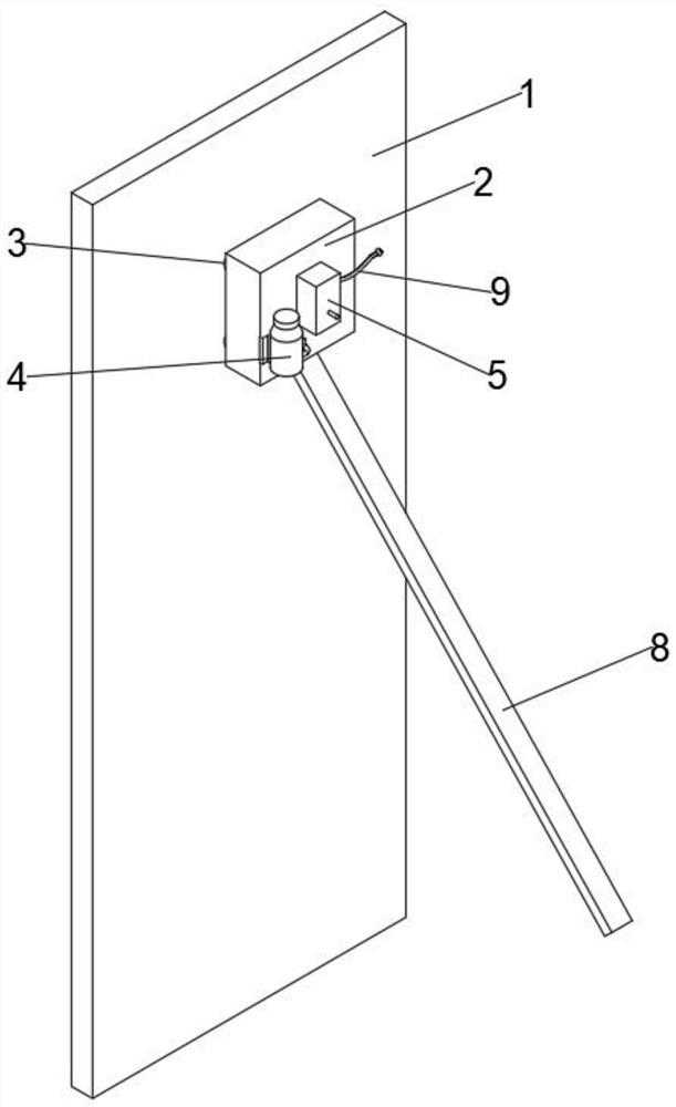
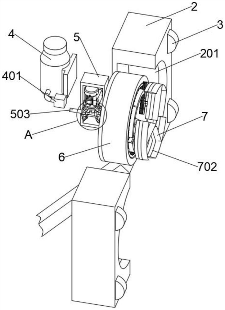
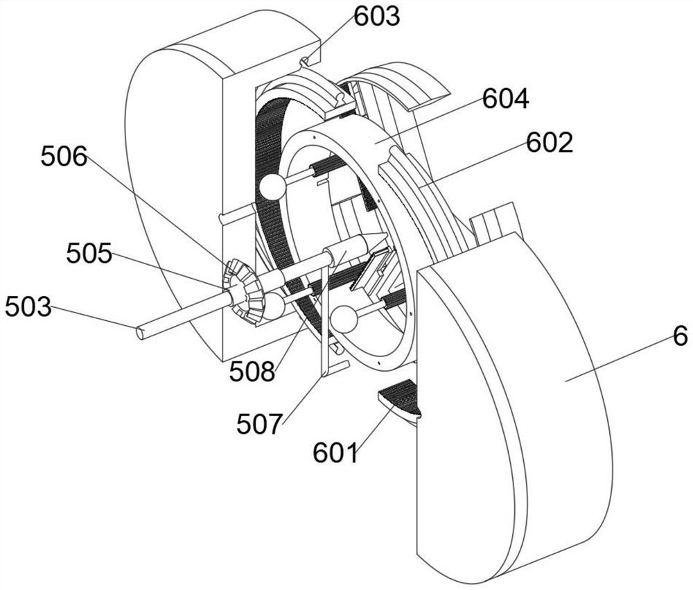
The invention discloses an anti-leakage method for stress crack control of a steel-concrete main body structure, and belongs to the technical field of building construction. The anti-leakage method for stress crack control of the steel-concrete main body structure is realized based on anti-leakage equipment for stress crack control of the steel-concrete main body structure. The anti-leakage equipment for stress crack control of the steel-concrete main body structure comprises a wall body, wherein a hollow shaft is rotationally connected to the middle position of the lower side of the interior of a mechanical box; the rear end of a sleeve penetrates through the inner wall of the mechanical box, extends into a circular groove and is sleeved with a rotating block; a guide rail is arranged in the middle of the circumferential outer wall of an annular rack; an empty groove is formed in the middle of the front side of a limiting block; and a flat scraping plate is hinged to the interior of the empty groove through a shaft. According to the anti-leakage method for stress crack control of the steel-concrete main body structure, the structures are tightly matched so that two actions can be continuously carried out, manpower and material resources are effectively saved, the scraping is more uniform, and the situation that water leaks from cracks to other residents, and the occurrence of the cracks causes great trouble to the residents is avoided.

Description

technical field [0001] The invention relates to the technical field of building construction, in particular to an anti-leakage method for controlling stress cracks of a steel-concrete main structure. Background technique [0002] In recent years, in the field of reinforced concrete structures, surface cracks after pouring of concrete structures have become a relatively common quality problem and a technical problem that needs to be solved urgently. Since the damage and collapse of structures under the action of external loads starts from the expansion of cracks, it is understandable that people often have a sense of fear of building damage to cracks. However, the appearance of a large number of cracks is not directly related to the load. Through a large number of investigations and field measurements, it has been proved that such cracks are caused by deformation, including temperature deformation, shrinkage deformation and uneven settlement deformation of the foundation. Th...

Claims


Application Information

Patent Timeline
IPC IPC(8): E04B2/00E04G23/02E04B1/66
CPCE04B2/00E04G23/0203E04B1/66
Inventor 周大伟贾岩辛星
Owner CHINA CONSTR FIFTH ENG DIV CORP LTD
Why Eureka
Try Eureka