Energy storage power station multi-branch system capable of achieving fault redundancy
An energy storage power station and multi-branch technology, which is applied in the field of energy storage power stations, can solve the problems that the use and operation of the sunshade mechanism is not simple and convenient, the energy storage power station system cannot effectively dissipate heat, and the fault redundancy can achieve good heat dissipation effect , Easy to operate and use, large ventilation area
- Summary
- Abstract
- Description
- Claims
- Application Information
AI Technical Summary
Problems solved by technology
Method used
Image

Examples
Embodiment 1
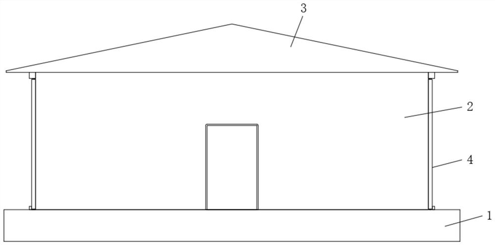
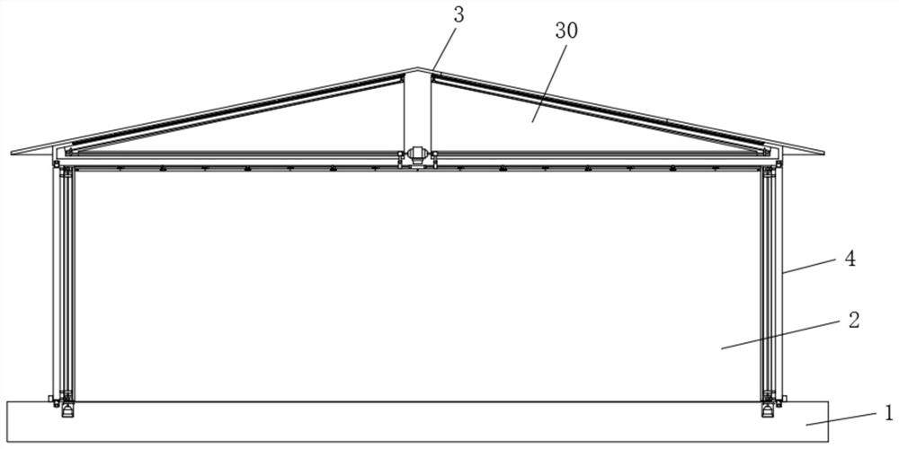
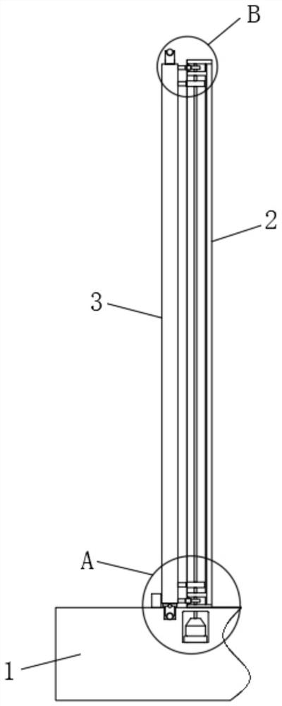
[0041] Embodiment one, by Figure 1 to Figure 9 as well as Figure 11 to Figure 15 Provide, the present invention comprises foundation boss 1, and both sides of foundation boss 1 top are all equipped with U-shaped wall 2, and ceiling 3 is installed between the tops of two U-shaped walls 2, and two U-shaped walls A movable wall 4 is installed between both ends of the body 2, and the energy storage power station and the multi-branch system of the energy storage power station can be installed in the area enclosed by two U-shaped walls 2 and two movable walls 4, that is, On the top of the foundation boss 1 and below the ceiling 3;
[0042] Both ends of the top of the foundation boss 1 and both ends of the bottom of the ceiling 3 are provided with a long groove 5, and one end of the top and bottom of the two movable walls 4 is equipped with a support shaft 6, and the support shaft 6 is movably inserted into the long groove 5, and the end of the support shaft 6 is equipped with a ...
Embodiment 2
[0044] Embodiment two, on the basis of embodiment one, by Figure 4 , Figure 5 and Figure 13 Given, a protective net 18 is installed between the ends of the two U-shaped walls 2, and a first thermal insulation board 19 is installed on the inner side of the two U-shaped walls 2, and the first thermal insulation board 19 Made of aluminum silicate fiberboard, through the setting of the protective net 18, it can effectively prevent people or animals from entering the movable wall 4 after it is opened, which will affect the safe use of the energy storage power station. Through the setting of the first thermal insulation board 19, it can Effective thermal insulation in low temperature weather.
Embodiment 3
[0045] Embodiment three, on the basis of embodiment one, by Figure 4 Given, the bottoms of the two movable walls 4 are equipped with long boards 20, and the bottoms of the long boards 20 are equidistantly equipped with small balls 21, so that the movable walls 4 can move effectively and can support the movable walls 4 Function, when the movable wall 4 moves, the small ball 21 will roll contact with the top of the foundation boss 1, so that the movement and rotation of the movable wall 4 will be more convenient and stable.
PUM
 Abstract
Description
Claims
Application Information