Acid squeezing device for oil well acidification and blockage removal

A technology for oil wells and installation casings, which is used in wellbore/well components, production fluids, earth-moving drilling, etc. It can solve the problems of dredging pipe pressure, waste of chemicals, affecting the effect of blocking removal, etc., so as to increase the service life and reduce the impact. force effect

Inactive Publication Date: 2021-06-25
孙淑芳
View PDF21 Cites 0 Cited by
  • Summary
  • Abstract
  • Description
  • Claims
  • Application Information

AI Technical Summary

Problems solved by technology

[0003] At this time, in order to ensure that the oil well will not be blocked, a device is usually used to remove the plugging operation inside the oil well. During the plugging operation, since the dredging pipe has been in hard contact with the inside of the oil well, it will cause the dredging pipe itself to be subject to greater pressure, and cause the outer surface of the dredging pipe to be subject to greater wear. After long-term use, it will cause The life of the dredge pipe itself is shortened, which affects the use
[0004] In the process of unblocking the oil well, the outer surface of the dredging pipe must always be in contact with the side of the oil well in order to achieve an effective unblocking and dredging effect. The diameter of the pipe itself is fixed, which leads to the fact that the dredging pipe cannot be in contact with the inner surface of the oil well for a long time during the actual dredging process. At this time, the dredging effect will be significantly reduced and the dredging efficiency will be affected.
[0005] At the same time, in order to ensure the dredging effect, chemical agents are generally used to dissolve the organic matter inside the oil well, and then dredging pipes and other devices are used to achieve the dredging effect. The distribution of chemical agents in various parts of the pump is not uniform. At this time, the plugging removal effect of chemical agents will be greatly reduced, resulting in waste of chemicals and affecting the plugging removal effect.

Method used


Image

  • Acid squeezing device for oil well acidification and blockage removal
  • Acid squeezing device for oil well acidification and blockage removal
  • Acid squeezing device for oil well acidification and blockage removal

Examples


Embodiment Construction

[0024] The following will clearly and completely describe the technical solutions in the embodiments of the present invention with reference to the accompanying drawings in the embodiments of the present invention. Obviously, the described embodiments are only some, not all, embodiments of the present invention. Based on the embodiments of the present invention, all other embodiments obtained by persons of ordinary skill in the art without making creative efforts belong to the protection scope of the present invention.

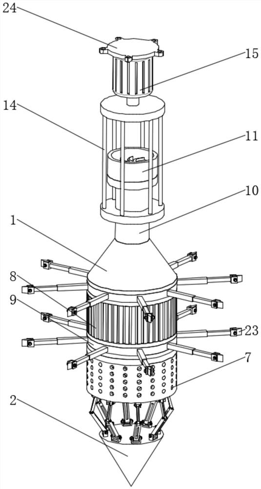
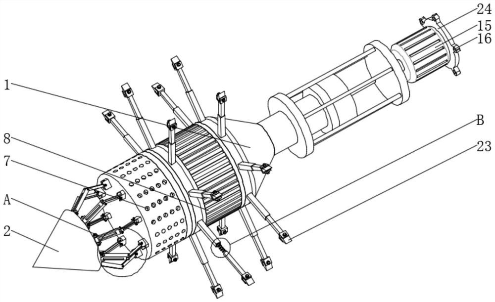
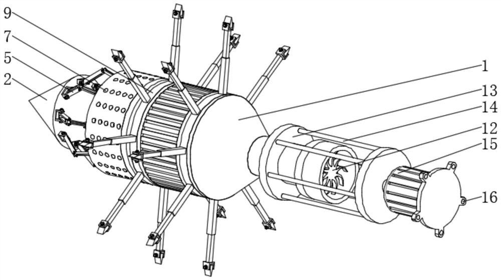
[0025] see Figure 1-6 , an acid squeezing device for oil well acidification and plugging removal, comprising a cylinder body 1, a nose cone 2 is arranged on the top of the cylinder body 1, and a fixing seat 3 is fixedly installed at an equal angle between the bottom end of the nose cone 2 and the top end of the cylinder body 1, and is located at The bottom of the fixed seat 3 at the bottom of the nose cone 2 is movably connected with the lower connecting rod ...


PUM


Abstract

The invention relates to the technical field of oil well development, and discloses an acid squeezing device for oil well acidification and blockage removal. The acid squeezing device comprises a cylinder body, wherein a head cone is arranged at the top end of the cylinder body, fixing seats are fixedly arranged at the bottom end of the head cone and the top end of the cylinder body at equal angles, the bottom end of the fixing seat located at the bottom end of the head cone is movably connected with a lower connecting rod, and the top end of the fixing seat located at the top end of the cylinder body is movably connected with an upper connecting rod. According to the acid squeezing device for oil well acidification and blockage removal, the head cone extends into an oil well, at the moment, the head cone can carry out wall breaking operation on the interior of the oil well, meanwhile, pressure is applied downwards, the downward pressure can be absorbed by the upper connecting rod and the lower connecting rod and is converted into relative rotation of the upper connecting rod and the lower connecting rod, and the upper connecting rod and the lower connecting rod are driven to rotate relative to the fixing seats to counteract part of the pressure, so that the impact force borne by the cylinder body is reduced, the service life is prolonged, and the advantage that the impact force borne by the device can be reduced is achieved.

Description

technical field [0001] The invention relates to the technical field of oil well development, in particular to an acid squeezing device for acidizing and plugging removal of oil wells. Background technique [0002] The oil well is the hole drilled according to the well layout system of the oilfield development plan for the exploitation of oil, and the oil rises from the bottom of the well to the wellhead. Oil wells are perforations drilled by drilling methods. Generally, after the oil well is drilled into the oil layer, the oil layer casing is lowered, and oil well cement is injected into the annular space between the casing and the well wall to maintain the well wall and seal the oil, gas, and water layers. The hole gun shoots through the oil layer to form a channel, which is lowered into the oil pipe, and the oil is raised from the bottom of the oil well to the head of the well by a suitable induction method. Oil and gas reservoirs are porous rock formations deep undergro...

Claims


Application Information

Patent Timeline
Patent Type & Authority Applications(China)
IPC IPC(8): E21B43/22E21B41/00
CPCE21B43/16E21B41/00
Inventor 孙淑芳
Owner 孙淑芳
Why Eureka
Try Eureka