Intelligent heat supply dynamic hydraulic balance control method

A technology of hydraulic balance and control method, which is applied in the direction of household heating, heating methods, and heating systems, and can solve problems such as high server computing performance requirements, high operating costs of heating systems, and large distribution areas of heating pipe networks. Achieve the effects of saving time for debugging pipe network, low heating operation cost, and low performance requirements

Pending Publication Date: 2021-06-25
WEIHAI LCARBO INTELLIGENT TECH CO LTD
View PDF8 Cites 6 Cited by
  • Summary
  • Abstract
  • Description
  • Claims
  • Application Information

AI Technical Summary

Problems solved by technology

[0004] The shortcomings of this structure and control method are as follows: first, it is necessary to place wireless remote temperature collectors in the homes of several users in each unit, and the number of heat users is large, which greatly increases the heating cost; second, the return water temperature of the unit The value and the room temperature value of the unit user need to be fed back to the server in real time. After the server passes the calculation, it will issue the valve opening change amount command to the automatic control unit of the balance valve. The automatic control unit of the balance valve will then control the mechanical transmission flow control unit to adjust the valve. Opening, in the process of adjusting the opening of the balance valve, the server must always participate. The heating pipe network has a large distribution area, and the server calculates and processes a lot of data, which takes a long time. There is a delay in data processing and transmission, and the server has high computing performance requirements. The thermal system is also expensive to run

Method used


Image

  • Intelligent heat supply dynamic hydraulic balance control method
  • Intelligent heat supply dynamic hydraulic balance control method
  • Intelligent heat supply dynamic hydraulic balance control method

Examples


Embodiment Construction

[0026] The present invention will be described below in conjunction with the accompanying drawings and embodiments.

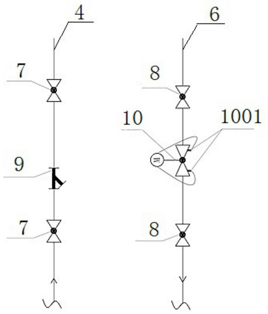
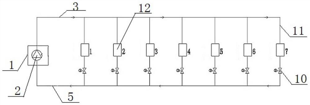
[0027] Such as figure 1 , figure 2 As shown, it simply shows the installation position of the intelligent dynamic balance valve in the secondary pipe network. The hot water flows out from the thermal station 1, enters the unit water supply riser 4 through the water supply pipe 3, passes through the unit heating user 12, and then passes through the unit return water Standpipe 6 flows back to thermal station 1 from return pipe 5; water supply ball valve 7 and water supply decontamination device 9 are installed on unit water supply standpipe 4, and return water ball valve 8 and intelligent dynamic balance valve 10 are installed on unit return water standpipe 6 The intelligent dynamic balance valve 10 is installed between two return water ball valves 8, and the pressure sensor 1001 and temperature sensor are installed on the intelligent dynamic balance valve 10. ...


PUM


Abstract

The invention discloses an intelligent heat supply dynamic hydraulic balance control method. The method comprises the steps that a circulating pump in a heating station is set to be in a constant pressure difference operation mode; the number of users with heating in each unit of a building is counted, and the actual total heating area of each unit is calculated; a flow coefficient of a set unit area is selected; and the flow coefficient of the unit area and the actual total heating area of each unit are input into an upper computer, and the upper computer calculates the total flow needed by each unit. The method has the advantages that the heat supply and energy saving effects are good, the phenomenon of uneven heat supply can be avoided, the heat supply quality is improved, the operation cost is saved, and the like.

Description

technical field [0001] The invention relates to the technical field of heating pipe network balance adjustment, in particular to an intelligent heating dynamic hydraulic balance control method. Background technique [0002] Most of the heating in northern cities in my country adopts centralized heating. With the improvement of economic level, the distribution area of ​​heating pipe network is getting larger and larger, and the number of heat users is also increasing sharply. The heating temperature of different areas or floors in the network varies greatly, the room temperature of the near-end users is high, and the room temperature of the far-end users is low. Even if the heat pump is overloaded, it will not help, the energy consumption is high, the operating cost is high, and the operating efficiency of the heating system is reduced. . [0003] In order to solve the above problems, in the prior art, there is a method of improving the heating effect by using a dynamic balanc...

Claims


Application Information

Patent Timeline
Patent Type & Authority Applications(China)
IPC IPC(8): F24D19/10
CPCF24D19/1015
Inventor 张晓宁蔺军义丛华成张文平初新刚赵玉伟李鸣
Owner WEIHAI LCARBO INTELLIGENT TECH CO LTD
Why Eureka
Try Eureka