
A method for correcting magnetic resonance k-space data

A data correction and K-space technology, which is applied in the computer field, can solve problems such as the correction of magnetic resonance receiving gain difference and phase difference, and the method of K-space data splicing without elaborating in detail.

Active Publication Date: 2021-12-21
UNIV OF ELECTRONICS SCI & TECH OF CHINA
View PDF8 Cites 0 Cited by
  • Summary
  • Abstract
  • Description
  • Claims
  • Application Information

AI Technical Summary

Problems solved by technology

However, the above technology does not elaborate on the K-space data splicing method, nor does it elaborate on the correction of the gain difference and phase difference of the magnetic resonance reception

Method used


Image

  • A method for correcting magnetic resonance k-space data
  • A method for correcting magnetic resonance k-space data
  • A method for correcting magnetic resonance k-space data

Examples


Embodiment Construction

[0042] To facilitate skilled in the art understand the technical contents of the present invention, the following further explanation of the present invention in conjunction with the accompanying drawings.

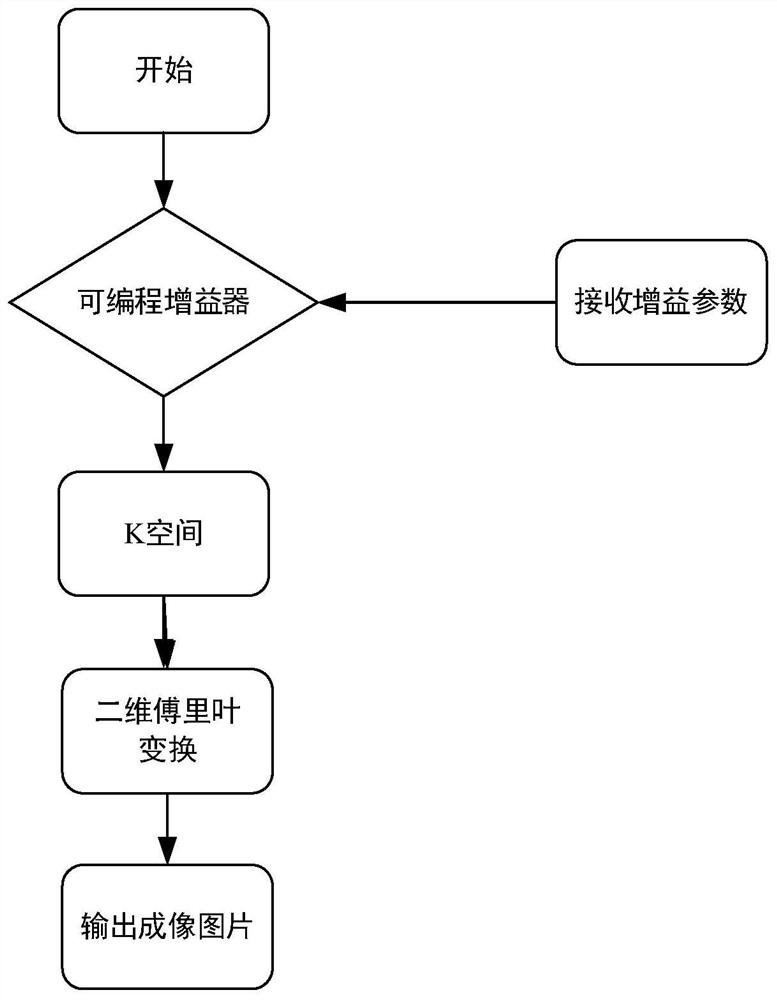
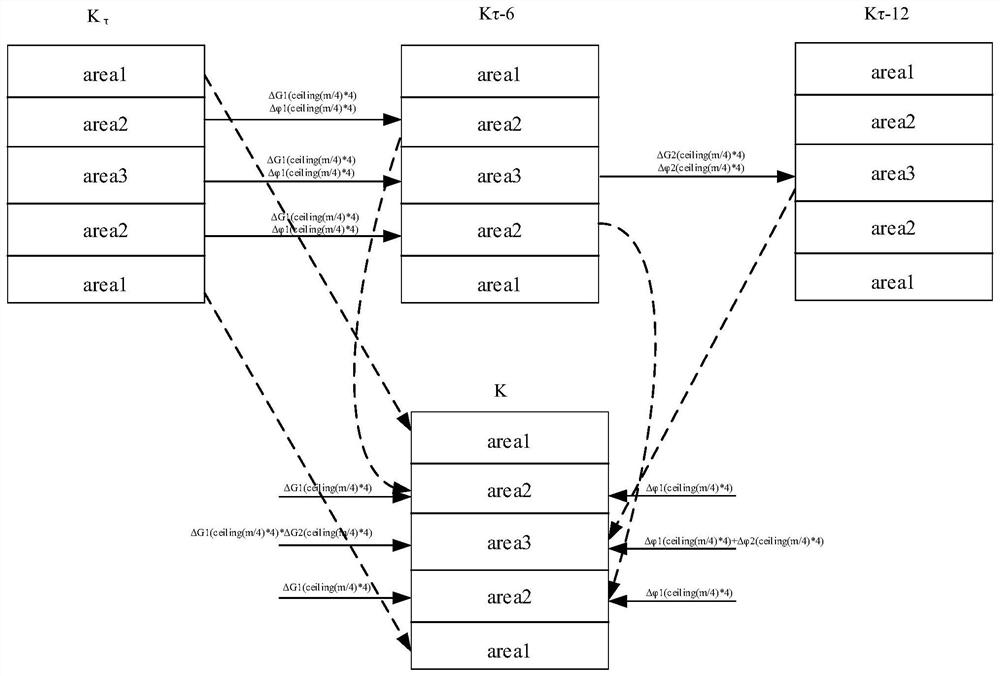
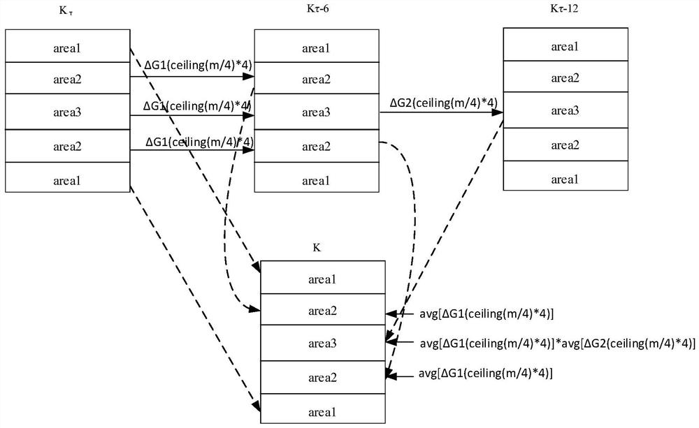
[0043] Scan data acquisition in the sequence, each receiving a gain control parameter adjustment, a sequential scan is performed, to obtain a raw K-space data set to obtain reception gain parameters are τdB, τ-6dB, τ-12dB three groups K spatial data Kτ, Kτ-6, Kτ-12. By analyzing the gain and phase differences of these three sets of data, the data space construct a mosaic image, the data space of the stitched image may be obtained by a Fourier transform, the system performs processes such as figure 1 Indicated.

[0044] The present invention proposes a K-space data obtained under different receive gain parameter spliced ​​into a method of K-space data, and the K space at different reception gain of a normalization parameter data receiving method in a gain parameter of the same....


PUM


Abstract

The invention discloses a method for correcting magnetic resonance K-space data, which is applied to the field of magnetic resonance K-space data processing. Aiming at the lack of a specific implementation method for K-space data splicing in the prior art, the invention performs gain and integration on the spliced ​​K-space data. Phase compensation, specifically: normalize the K-space data under three different gain parameters to the same receiving gain level through gain difference correction and compensation; then perform phase difference correction and compensation on the K-space data after gain compensation.

Description

Technical field [0001] The present invention belongs to the technical field of computer, and more particularly to a magnetic resonance K spatial data processing technology. Background technique [0002] In the echo signal of all phase codes in the MRIK space, the echo signal amplitude of each phase coding row has a significant difference, and the larger phase coding line is smaller than the phase coding line signal is small, so the gain setting is set. In the process, the fixed reception gain is set to ensure that the entire phase coding row return amplitude is the maximum point of the row, the overall echo signal is not up to the maximum signal dynamic range. Mark A et al. And Choh et al. Found that the phase coding line of different regions of K space in different reception gain parameters is guaranteed to be a small line of the phase encoding. The echo signal does not overflow, and the echo signal in which the larger phase coding line is located to achieve a greater dynamic ra...

Claims


Application Information

Patent Timeline
Patent Type & Authority Patents(China)
IPC IPC(8): G01R33/48G01R33/58
CPCG01R33/4818G01R33/58
Inventor 吴林刘杭余洁张涛尧德中解玺洁胡霞飞
Owner UNIV OF ELECTRONICS SCI & TECH OF CHINA
Learn More