
Multipath fiber spectrometer system based on DSP and FPGA

A fiber optic spectrometer, multi-channel technology, applied in the field of spectrometer, can solve the problems of small parameter range, increase the cost of measurement system, difficult operation, etc., and achieve the effect of high signal-to-noise ratio, good long-term stability, and large signal dynamic range

Inactive Publication Date: 2016-02-17
郭洪
View PDF1 Cites 3 Cited by
  • Summary
  • Abstract
  • Description
  • Claims
  • Application Information

AI Technical Summary

Problems solved by technology

If multiple spectrometers are used to work at the same time, it will not only bring difficulties to the operation, but also increase the cost of the measurement system; the current spectrum detector can measure a small range of parameters, refer to the Chinese invention patent, the patent number is 201210103294.1, which discloses a micro The hole spectrometer includes a signal processor, a precision swing rod, an optical fiber, and a lens base, the signal processor is connected to the lens base, the lens base is connected to a precision swing rod, and the precision swing rod is connected to an optical fiber, and it is characterized in that: A signal processing circuit board is arranged inside the signal processor, and a housing is provided outside the signal processing circuit board, and a USB interface is provided on the housing, the lens base is arranged on the upper surface of the housing, and a lens is arranged on the lens base groove, a convex lens is set in the lens groove, a fiber hole is set on the precision swing rod, a limit bolt is set under the precision swing rod, a metal protection head is provided at the front end of the fiber, and the metal protection head is inserted into the fiber hole. The above limit nut fixes the metal protective head through threaded connection

Method used


Image

  • Multipath fiber spectrometer system based on DSP and FPGA
  • Multipath fiber spectrometer system based on DSP and FPGA

Examples


Embodiment Construction

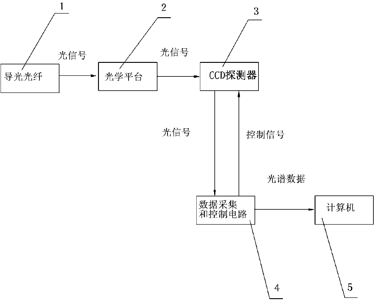
[0018] Such as figure 1 Shown is a structural block diagram of a multi-channel optical fiber spectrometer system based on DSP and FPGA in the present invention. The figure includes: light guide fiber 1, optical platform 2, CCD detector 3, data acquisition and control circuit 4, computer 5; Focus on the photosensitive surface of the CCD detector 3 after processing, after receiving the light split by the CCD detector 3, convert the spectral signal into an electrical signal output; the output electrical signal is processed by the data acquisition and control circuit 4, and then output and sent to In the computer 5, the computer 5 finally displays the spectral graph; the obtained spectral data can be used for various subsequent analysis, processing and control.

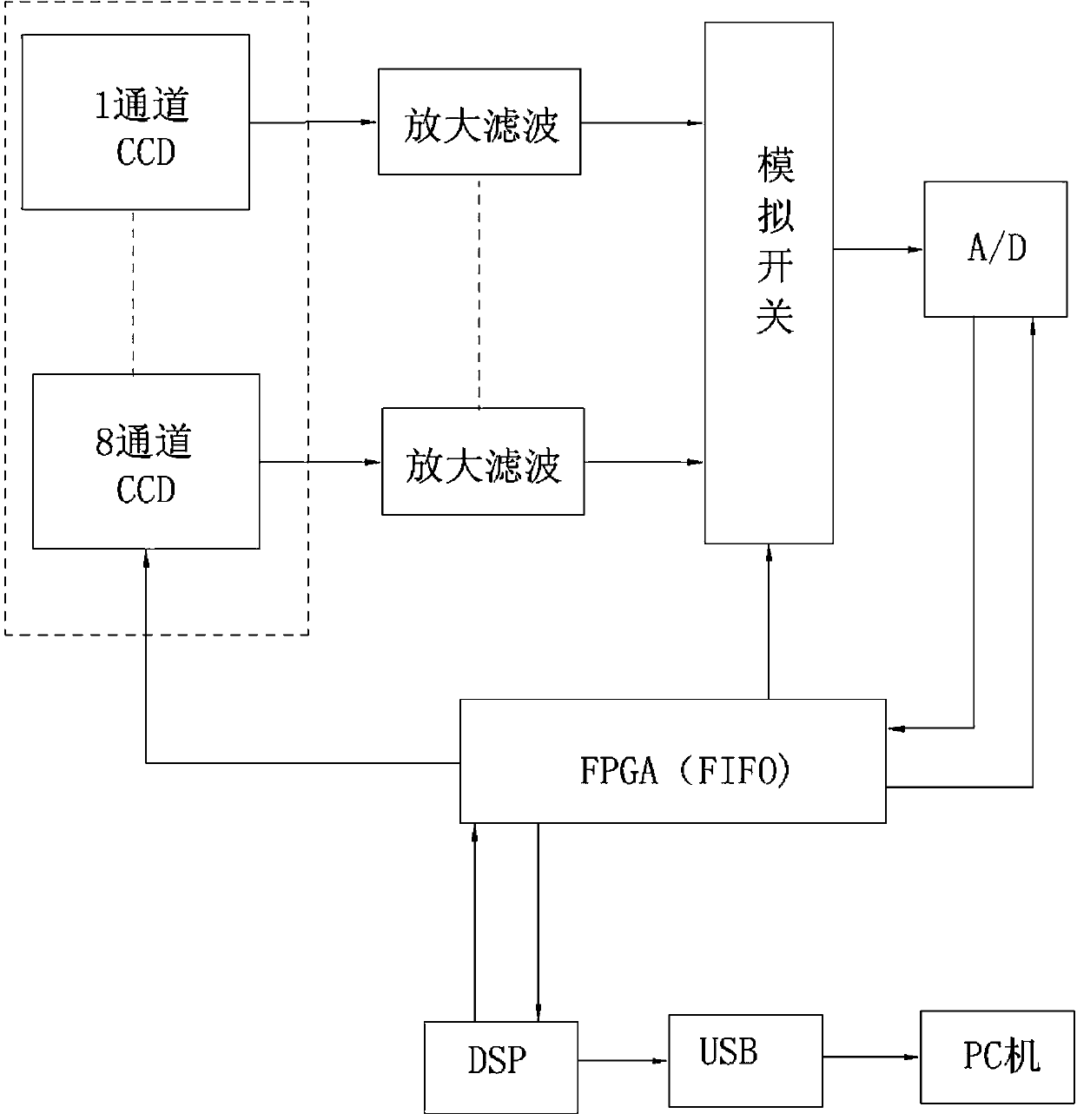
[0019] The data acquisition and control circuit 4 of the present invention is made of filter amplifying circuit, eight select one analog switch and A / D converter, carries out the electric signal that CCD detector 3 sends...


PUM


Abstract

The invention relates to a multipath fiber spectrometer system based on a DSP and an FPGA. According to the multipath fiber spectrometer system based on the DSP and the FPGA, a multipath spectrum splitting system is combined with the single electronic signal processing module technology, an advantage of compact structure of a single-channel spectrometer is not only realized, but also real-time and synchronous sampling processing between various paths of spectrum signals can be realized, and remarkable technology advantages are realized. The multipath fiber spectrometer system based on the DSP and the FPGA comprises a light guiding fiber, an optical platform, a CCD detector, a data acquisition and control circuit and a computer and is characterized in that, signal light is led in through the light guiding fiber and enters the optical platform, light splitting is realized through the optical platform, after light splitting processing, the light is focused on a photosensitive face of the CCD detector, after reception through the CCD detector and light splitting, a spectrum signal is converted into an electrical signal which is outputted, the outputted electrical signal is processed through the data acquisition and control circuit and is then transmitted to the computer, a spectrum graph is displayed through the computer, and the acquired spectrum data can be used for subsequent analysis, processing and control.

Description

technical field [0001] The invention relates to a spectrometer used in various occasions for measuring spectra and related parameters, in particular to a multi-channel optical fiber spectrometer system based on DSP and FPGA. Background technique [0002] Over the past century, spectral analysis techniques have become diversified. In addition to emission, absorption, reflection, fluorescence, and scattering spectroscopy methods, differential spectroscopy, modulation spectroscopy, Fourier transform, and interference spectrometers have also been developed. [0003] With the development of spectroscopic instrument hardware, the measurable wavelength range has also expanded accordingly, from long-wave to millimeter-wave, and short-wave to soft X-ray (10nm). Since the 1990s, a fiber optic spectrometer with a microstructure has attracted the attention of many people, and has been widely used in various spectral measurement and related fields. Compared with traditional large-scale ...

Claims


Application Information

Patent Timeline
Patent Type & Authority Applications(China)
IPC IPC(8): G01J3/28
Inventor 郭洪
Owner 郭洪
Learn More