
Optical cable stripping device

A technology of stripping device and optical cable, applied in the direction of light guide, optics, optical components, etc., can solve the problems of poor controllability of cutting depth, poor stripping effect, damaged optical fiber, etc. Easy-to-use effects

Active Publication Date: 2021-06-25
HANGZHOU FUTONG COMM TECH CO LTD
View PDF18 Cites 0 Cited by
  • Summary
  • Abstract
  • Description
  • Claims
  • Application Information

AI Technical Summary

Problems solved by technology

[0006] In order to solve the problems of poor controllability of cutting depth and low precision in the existing optical cable stripping device, it is easy to cause problems such as too shallow cutting, poor stripping effect, or damage to the optical fiber due to too deep cutting during the process of cutting and stripping the optical cable cortex , the invention provides an optical cable stripping device

Method used


Image

  • Optical cable stripping device
  • Optical cable stripping device
  • Optical cable stripping device

Examples


Embodiment

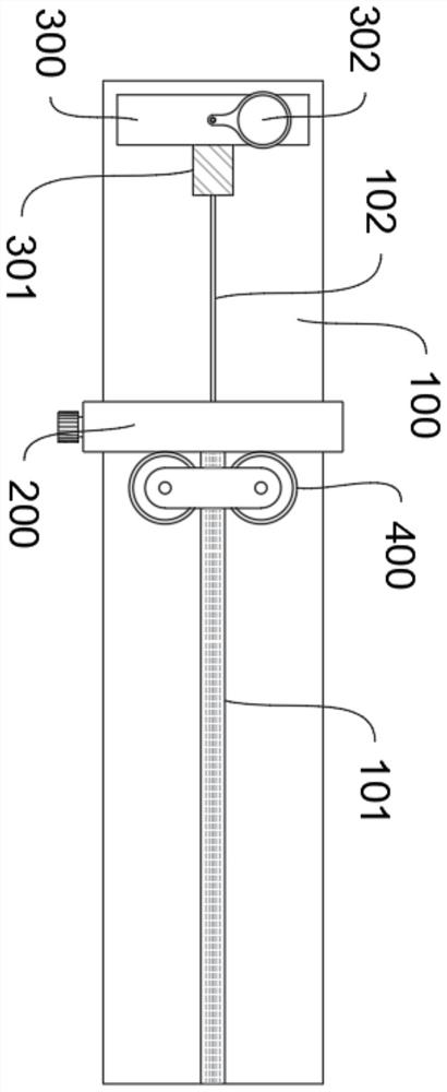
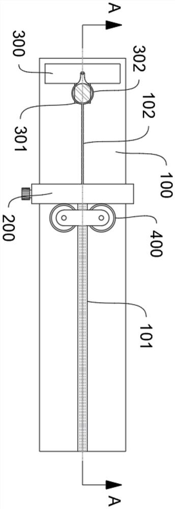
[0050] a kind of like figure 1 , figure 2 and image 3 The shown optical cable stripping device specifically includes:

[0051] The base 100, the base 100 is provided with a stripper 200 for stripping the cortex of the optical cable 500, and an observation assembly 300 for improving the stripping accuracy, the stripper 200 and the observation assembly 300 are fixedly arranged on the base 100;

[0052] The base 100 is provided with a cable inlet trough 101, the upper end of the cable inlet trough 101 is opened to place the optical cable 500, and extends from the edge of the base 100 to the wire stripper 200, and further a fiber outlet trough 102 can be set on the base 100, as shown in the present invention. The embodiment is provided with extending from the wire stripper 200 to the observation assembly 300;

[0053] The observation assembly 300 includes a platform, and the side of the platform facing the wire stripper 200 is provided with a reflective observation mirror 301...


PUM


Abstract

The invention belongs to the field of optical cable processing equipment, and particularly relates to an optical cable stripping device. The optical cable stripping device comprises a base, the base is provided with a wire stripper used for stripping a sheath layer of an optical cable and an observation assembly used for improving the wire stripping precision, and the wire stripper and the observation assembly are both fixedly arranged on the base. The observation assembly comprises a seat stand, and a reflective observation mirror is arranged on one side, facing the wire stripper, of the seat stand. A wire passing hole is formed in the wire stripper main body, the wire passing hole is a through hole, the axial direction of the wire passing hole points to the reflective observation mirror of the observation assembly, and a pair of telescopic wire stripping knives is arranged on the side walls of the two sides of the wire passing hole; And the wire stripping knife is matched with a transmission structure to realize synchronous feeding or retracting. According to the invention, micron-sized accurate cutting depth control can be realized under the condition of manual operation. The device has good applicability to layer-stranded optical cables of different specifications, sizes and models.

Description

technical field [0001] The invention belongs to the field of optical cable processing equipment, in particular to an optical cable stripping device. Background technique [0002] Optical cables are manufactured to meet optical, mechanical or environmental performance specifications. It is a communication cable assembly that uses one or more optical fibers placed in a sheath as a transmission medium and can be used individually or in groups. [0003] Under normal circumstances, the cortex of the optical cable is an important part of protecting the optical fiber inside, but in some specific occasions or specific use requirements, the cortex of the optical cable needs to be cut and stripped. [0004] For example, during the installation, maintenance and fault detection of optical cables, it is usually necessary to cut a window radially in the optical cable cortex so that the optical fibers inside can be taken out. Another example is that during the construction and wiring proc...

Claims


Application Information

Patent Timeline
Patent Type & Authority Applications(China)
IPC IPC(8): G02B6/245
CPCG02B6/245Y02W30/82
Inventor 何园园王醒东
Owner HANGZHOU FUTONG COMM TECH CO LTD
Learn More