Optical filter

An optical filter and optical filter technology, applied in the field of optical filters, can solve the problems of non-tunable free spectral region, unable to meet the flexibility requirements of optical filter free spectral region, etc. and the effect of bandwidth

Active Publication Date: 2021-06-25
INST OF SEMICONDUCTORS - CHINESE ACAD OF SCI
View PDF19 Cites 6 Cited by
  • Summary
  • Abstract
  • Description
  • Claims
  • Application Information

AI Technical Summary

Problems solved by technology

[0003] Existing technical solutions focus on the research on the tunable characteristics of the central wavelength and filtering bandwidth of optical filters. Common research results include optical filters made of fiber Bragg gratings, Mach-Zehnder, and microring resonators. devices, but the above optical filters ignore the impact of the flexibility of the free spectral region on

Method used


Image

  • Optical filter
  • Optical filter
  • Optical filter

Examples


Embodiment Construction

[0031] Hereinafter, embodiments of the present disclosure will be described with reference to the drawings. It should be understood, however, that these descriptions are exemplary only, and are not intended to limit the scope of the present disclosure. In the following detailed description, for purposes of explanation, numerous specific details are set forth in order to provide a thorough understanding of the embodiments of the present disclosure. It may be evident, however, that one or more embodiments may be practiced without these specific details. Also, in the following description, descriptions of well-known structures and techniques are omitted to avoid unnecessarily obscuring the concept of the present disclosure.

[0032] The terminology used herein is for the purpose of describing particular embodiments only, and is not intended to be limiting of the present disclosure. The terms "comprising", "comprising", etc. used herein indicate the presence of stated features, ...


PUM


Abstract

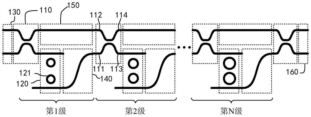
The invention provides an optical filter, comprising N+1 stages of optical switches, wherein each stage of optical switch comprising a first input end, a second input end, a first output end and a second output end; N stages of second-order micro-ring optical filter units, wherein each stage of second-order micro-ring optical filter unit comprises two micro-ring resonant cavities, the radiuses of the micro-ring resonant cavities of the N stages of second-order micro-ring optical filter units are different, and the kth-stage second-order micro-ring optical filter unit is connected with the first output end of the kth-stage optical switch; an input optical waveguide unit which is used for inputting a received optical signal into the first-stage optical switch; an N-stage first waveguide, wherein a kth-stage first waveguide is connected with the output end of the kth-stage second-order micro-ring optical filter unit and the first input end of a (k+1)th-stage optical switch; an N-stage second waveguide, wherein a kth-stage second waveguide is connected with the second output end of the kth-stage optical switch and the second input end of the (k+1) th-stage optical switch; and an output optical waveguide unit which is connected with the (N+1)th-stage optical switch and is used for outputting the filtered optical signal.

Description

technical field [0001] The present disclosure relates to the technical field of optical fiber communication, and more particularly, relates to an optical filter. Background technique [0002] The reconfigurable optical add-drop multiplexer is an important part of realizing the flexible optical communication network represented by the wavelength division multiplexing network, and the flexible optical communication network is very important for the gridless characteristics of the reconfigurable optical add-drop multiplexer. The need, and thus the demand for optical filters with high flexibility and tunable filtering. [0003] Existing technical solutions focus on the research on the tunable characteristics of the central wavelength and filtering bandwidth of optical filters. Common research results include optical filters made of fiber Bragg gratings, Mach-Zehnder, and microring resonators. However, the above-mentioned optical filters ignore the influence of the flexibility o...

Claims


Application Information

Patent Timeline
IPC IPC(8): G02B6/293
CPCG02B6/29395G02B6/29343G02B6/2934
Inventor 牛佳琪付鑫杨林
Owner INST OF SEMICONDUCTORS - CHINESE ACAD OF SCI
Why Eureka
Try Eureka