
Objective optical system

An optical system and objective lens technology, applied in the field of optical systems, can solve the problems of inconvenient adjustment of microscope height, rotation angle and focus position of objects, poor use effect, etc., and achieve the effect of convenient focus adjustment and convenient movement.

Pending Publication Date: 2021-06-25
南京甬宁科学仪器有限公司
View PDF7 Cites 1 Cited by
  • Summary
  • Abstract
  • Description
  • Claims
  • Application Information

AI Technical Summary

Problems solved by technology

[0004] The microscope device of the above optical system has the advantage of being able to configure the left and right optical systems in parallel; however, the microscope device of the above optical system still has some disadvantages, such as: it is inconvenient to adjust the height of the microscope, the angle of rotation and the focus of the object poor location

Method used


Image

  • Objective optical system
  • Objective optical system
  • Objective optical system

Examples


Embodiment Construction

[0031] The following will clearly and completely describe the technical solutions in the embodiments of the present invention with reference to the accompanying drawings in the embodiments of the present invention. Obviously, the described embodiments are only some, not all, embodiments of the present invention. Based on the embodiments of the present invention, all other embodiments obtained by persons of ordinary skill in the art without making creative efforts belong to the protection scope of the present invention.

[0032] see Figure 1-Figure 5 , the invention provides an objective optical system, wherein the technical scheme is as follows:

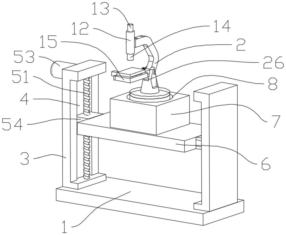
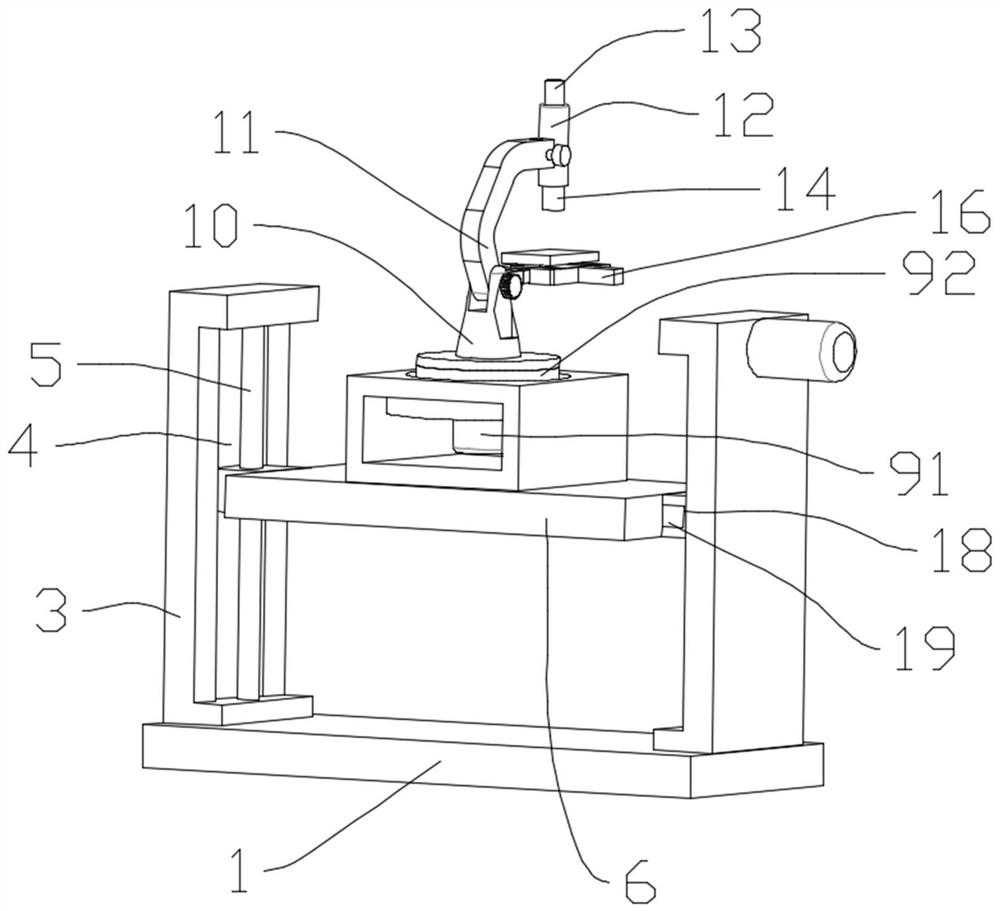
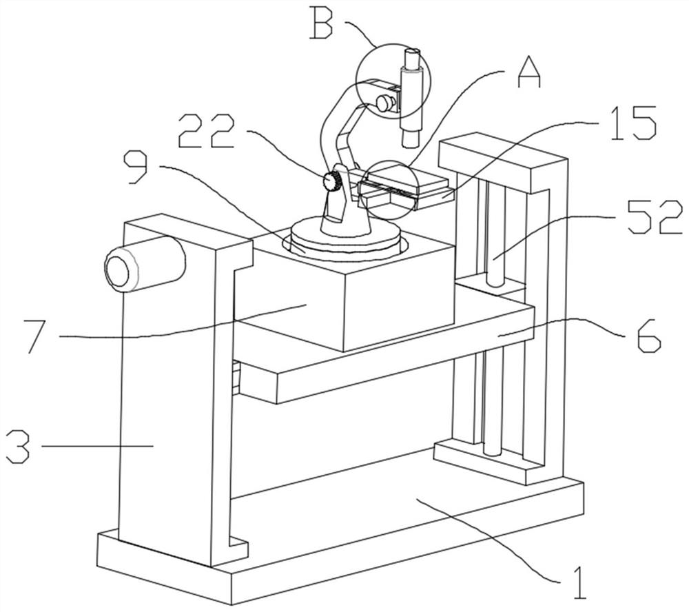
[0033] It includes a base 1 for installing the microscope body 2. Two symmetrical mounting plates 3 are fixedly installed on the upper surface of the base 1. The two mounting plates 3 are all provided with a first mounting groove 4, and the first mounting groove 4 is installed with The first moving mechanism 5, the supporting plate...


PUM


Abstract

The invention discloses an objective lens optical system. The objective lens optical system is characterized by comprising a base for mounting a microscope body; two symmetrical mounting plates are fixedly mounted on the upper surface of the base, and first mounting grooves are formed in the two mounting plates; and a first moving mechanism is mounted in the first mounting groove. A supporting plate is mounted on the first moving mechanism, an adjusting seat is fixedly mounted on the supporting plate, a second mounting groove is formed in the upper surface of the adjusting seat, a rotating mechanism is arranged in the second mounting groove, and the microscope body is fixedly mounted on the rotating mechanism. The microscope body comprises a rotating seat, a microscope arm, a lens barrel, an electronic eyepiece, an objective lens and a carrier bracket, so that the overall height of the microscope body can be adjusted conveniently. According to the system, an operator can conveniently adjust the horizontal rotation angle of the microscope body according to different illumination intensities.

Description

technical field [0001] The invention relates to the field of optical systems, in particular to an objective optical system. Background technique [0002] An optical system refers to a system composed of various optical elements such as lenses, mirrors, prisms, and diaphragms in a certain order. Usually used for imaging or optical information processing. The optical system composed of two or more refracting (or reflecting) spherical surfaces whose curvature centers are on the same straight line is called a coaxial spherical system, and the straight line where the curvature center is called the optical axis. [0003] For example, the Chinese patent with the authorized notification number CN102640031A discloses a kind of inclining stereomicroscope device that can parallelly configure the imaging of the left and right optical systems while retaining the advantages of the completely independent optical path for the right eye and the left eye. An optical system and a microscope ...

Claims


Application Information

Patent Timeline
Patent Type & Authority Applications(China)
IPC IPC(8): G02B21/02G02B21/24G02B21/26
CPCG02B21/02G02B21/24G02B21/26
Inventor 姜宁枫周蓓
Owner 南京甬宁科学仪器有限公司
Learn More