
Hair drier with high wind speed

A hair dryer, high wind speed technology, applied in the direction of washing hair or scalp devices, clothing, hairdressing equipment, etc., can solve the problems of increasing energy consumption, occupying handle space, large volume, etc., achieving simple structure, improving air intake and volume. small effect

Pending Publication Date: 2021-06-29
最火科技(杭州)有限公司
View PDF0 Cites 1 Cited by
  • Summary
  • Abstract
  • Description
  • Claims
  • Application Information

AI Technical Summary

Problems solved by technology

The handle of the hair dryer is usually cylindrical or almost cylindrical, and there is an air inlet under the handle. The inside of the handle becomes the air inlet channel of the hair dryer. The handle needs to be completely sealed. There are usually multiple buttons on the handle, and these buttons are connected to the mechanical Function switch 9, and these mechanical function switches generally have many internal parts and are large in size, thus occupying the space in the handle and reducing the cross-sectional area of ​​the air inlet channel in front of the connection between the handle and the blower
When the motor rotates at a high speed, the inhaled high-speed air flow will be blocked by the function switch before entering the fan cylinder, resulting in slowing down of the wind speed, and when the high-speed air flow is blocked by the function switch, high-decibel noise will be generated, increasing energy consumption

Method used


Image

  • Hair drier with high wind speed
  • Hair drier with high wind speed
  • Hair drier with high wind speed

Examples


Embodiment 1

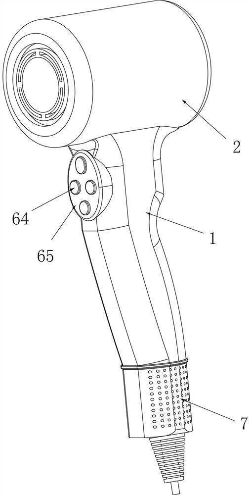
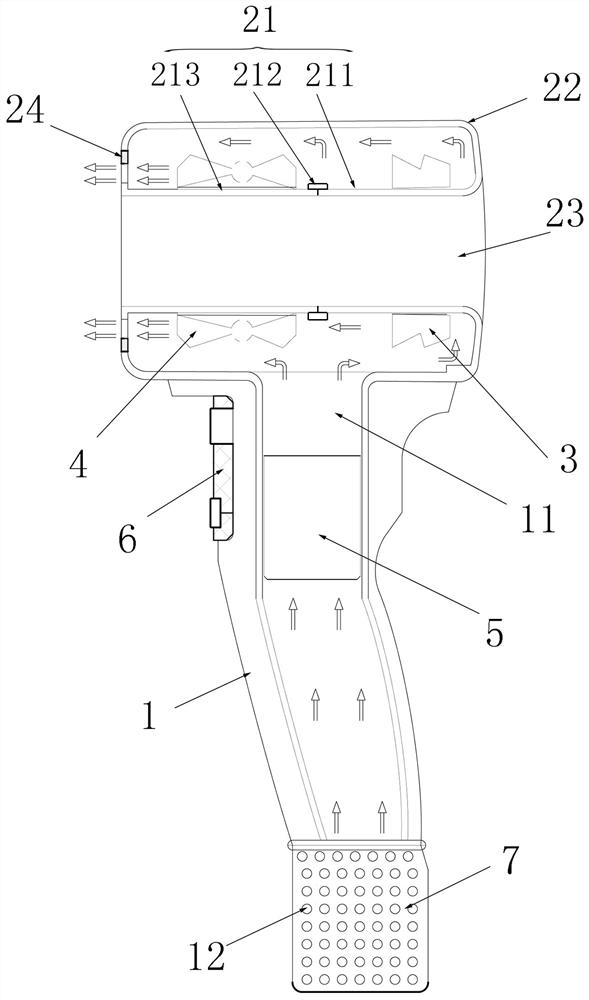
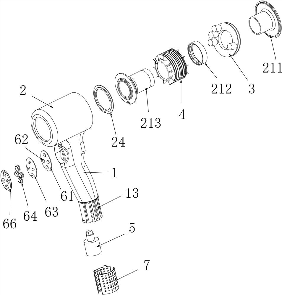
[0024] The hair dryer described in this embodiment includes a blower 2 and a handle 1, both of which are fixed as one. The air cylinder 2 includes an inner air duct 21 and an outer air duct 22 arranged coaxially, and the inner air duct 21 is composed of an air inlet inner pipe 211, a sleeve pipe 212 and an air outlet inner pipe 213 arranged coaxially, and the inner air inlet pipe 213 It is integrated with the air outlet inner pipe by a sleeve; an annular cavity 23 is formed between the outer wall of the inner air duct and the inner wall of the outer air duct, and the annular cavity 23 communicates with the inside of the handle 1; inside the annular cavity 23 There is also a control module 3 and a controllable heating element 4. The controllable heating element includes a tubular support and a heating wire wound on the support. The tubular support is set outside the air outlet inner tube 213. The control module 3 is a ring structure and is set on the inlet. On the outside of th...

Embodiment 2

[0031] The structure of this embodiment is similar to that of Embodiment 1, the difference is that: the end of the handle 1 is provided with a circular or elliptical air inlet pan 8 , and the bottom surface of the air inlet pan is a circular or elliptical filter screen 81 . When in use, the air enters directly from the bottom surface of the handle, and the air can be absorbed by the motor without changing the flow direction, so that the wind force of the hair dryer is stronger.


PUM


Abstract

The invention discloses a high-wind-speed hair drier which comprises an air duct and a handle which are fixed into a whole. A motor provided with fan blades is arranged in the handle and drives the fan blades to rotate, the air inlet end of the motor faces an air inlet in the tail end of the handle, and the air outlet end of the motor faces the handle and a connecting port of the air duct. A switch mounting position is arranged on the outer side of one end, close to the air duct, of the handle; a function switch is arranged in the switch mounting position; an air supply channel is arranged between the air outlet end of the motor and the connecting port of the air duct, and the ventilation area of each cross section of the air supply channel is larger than or equal to the cross section area of the air outlet end of the motor. The switch mounting position is arranged on the outer side of the handle, so that the function switch is prevented from occupying the space on the inner side of the handle, the cross sectional area of the air supply channel in the handle is maximized, the internal space of the handle can be completely utilized, the air inlet amount of the hair dryer is greatly increased, and hair can be rapidly dried.

Description

technical field [0001] The invention belongs to the technical field of hair drying devices, in particular to a hair dryer with high wind speed. Background technique [0002] Hairdryer generally comprises blower 2 and handle 1 (as Figure 10 As shown), the air cylinder 2 is provided with a heating wire assembly and a control module 3, and the handle 1 is provided with a motor 5 with fan blades. The handle of the hair dryer is usually cylindrical or almost cylindrical, and there is an air inlet under the handle. The inside of the handle becomes the air inlet channel of the hair dryer. The handle needs to be completely sealed. There are usually multiple buttons on the handle, and these buttons are connected to the mechanical Function switch 9, and these mechanical function switches generally have many internal parts and are large in size, thereby occupying the space in the handle and reducing the cross-sectional area of ​​the air inlet passage before the connection between the ...

Claims


Application Information

Patent Timeline
Patent Type & Authority Applications(China)
IPC IPC(8): A45D20/10A45D20/12
CPCA45D20/10A45D20/12
Inventor 叶军忠刘玉军
Owner 最火科技(杭州)有限公司
Learn More