A kind of drilling equipment with automatic adjustment of drilling angle

A technology of automatic adjustment and drilling equipment, applied in drilling/drilling equipment, boring/drilling, metal processing equipment, etc., can solve problems such as affecting the adjustment of the drill bit, deviation of drilling accuracy, and slippage of the transmission belt. To achieve the effect of good water stain collection effect

Active Publication Date: 2022-05-20
YANTAI XINCHAO FOUNDRY CO LTD
View PDF0 Cites 0 Cited by
  • Summary
  • Abstract
  • Description
  • Claims
  • Application Information

AI Technical Summary

Problems solved by technology

[0004] When the drilling machine is carried by personnel to the colder outdoor operation, because the transmission belt is running the equipment, it will continuously drive the auxiliary drill bit for adjustment and drilling, and friction will be generated between the turret and heat, and the gas with a lower temperature will adhere to the When the transmission belt is on it, it will liquefy when it is heated, causing the transmission belt to slip, affecting the adjustment of the drill bit, and causing deviations in drilling accuracy

Method used


Image

  • A kind of drilling equipment with automatic adjustment of drilling angle
  • A kind of drilling equipment with automatic adjustment of drilling angle
  • A kind of drilling equipment with automatic adjustment of drilling angle

Examples


Embodiment 1

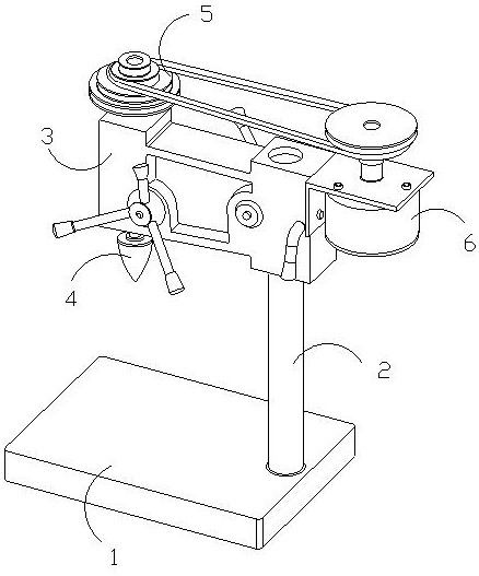
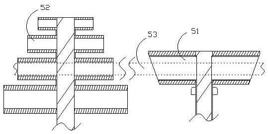
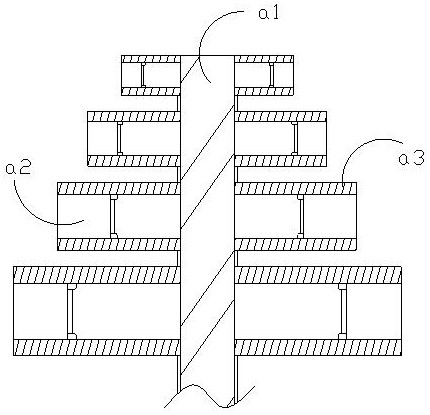
[0031] as attached figure 1 to attach Figure 7 Shown:

[0032] The present invention provides a kind of drilling equipment with automatic adjustment of drilling angle. The lower end is embedded in the support platform 1, the upper end of the vertical column 2 is connected with the adjustment column 3 and is movably matched, the drilling head 4 passes through the adjustment column 3 and moves below it, and the top frame 5 is installed on the adjustment column 3. The top position of the column 3, the motor 6 is fixedly installed on one side of the adjusting column 3.

[0033] The top frame 5 is provided with a right axle platform 51, an adjustment platform 52, and a speed control transmission belt 53. The adjustment platform 52 is located at one side of the right axis platform 51, and the speed control transmission belt 53 is connected to the right axis by transmission. Platform 51, the outer periphery of adjustment frame platform 52 and movable cooperation.

[0034] Wherei...

Embodiment 2

[0041] as attached Figure 8 to attach Figure 9 Shown:

[0042] Wherein, the inner abutment ring a33 is provided with a solid ring frame q1, an opening and closing plate q2, a telescopic frame q3, and a water collection cavity q4, and the solid ring frame q1 and the inner abutment ring a33 are an integrated structure and are arranged at its outer peripheral position. , the opening and closing plate q2 is hingedly connected to the solid ring frame q1, the water collection chamber q4 is located inside the solid ring frame q1, the telescopic frame q3 is connected between the solid ring frames q1 and is movably matched, and the solid ring frame q1 It is a ring structure with interval openings. There are eight telescopic frames q3, which are flexible. The opening and closing plates q2 are only opened inward. The water collection chamber q4 is in a hollow groove state. The telescopic frames The expansion and contraction deformation of q3 is beneficial to the circular displacement...


PUM


Abstract

The invention discloses a drilling equipment for automatically adjusting the drilling angle. The upper end of the column is connected with the adjustment column and cooperates with the movement. The drilling head passes through the adjustment column and moves below it, and rotates through the inner contact ring. The auxiliary interference device and the speed control transmission belt produce ring-shaped interference. As the wiper block is pressed and slides sideways, the resulting deformation creates a certain supporting force on the friction device, which is convenient for the friction device to touch the section surface of the speed control belt. It can wipe the water stains on the cross section, and the repulsive force generated by the magnetic ball and the elastic force of the spring form an interactive force to assist the deformation of the solid block, which is beneficial to its reset, and further has a tendency to drive the wiper block, so that it has its own compression Activities, and the water stains are squeezed out and then drained downward.

Description

technical field [0001] The invention belongs to the field of drilling, and more specifically relates to a drilling device for automatically adjusting the drilling angle. Background technique [0002] With the progress of the times, the processing of products is also constantly increasing the requirements, and the processing technology is gradually improving and developing. The drilling equipment with automatic adjustment of drilling angle is a commonly used equipment in component drilling. Its automatic angle adjustment can make the drill flexible. Drill components to create more precise holes. [0003] Based on the inventor's discovery above, the existing drilling equipment for automatically adjusting the drilling angle has the following deficiencies: [0004] When the drilling machine is carried by personnel to the colder outdoor operation, since the transmission belt is running the equipment, it continuously drives the auxiliary drill bit for adjustment and drilling, and...

Claims


Application Information

Patent Timeline
Patent Type & Authority Patents(China)
IPC IPC(8): B23B39/00B23B47/16B23Q11/00
CPCB23B39/00B23Q11/00B23Q5/10
Inventor 张蕾
Owner YANTAI XINCHAO FOUNDRY CO LTD
Why Eureka
Try Eureka