Submerged flow pushing device based on rail-abutted single pulley sliding

A submersible flow propeller, slip-type technology, applied in chemical instruments and methods, biological water/sewage treatment, water/sludge/sewage treatment, etc. production costs, etc.

Inactive Publication Date: 2017-03-15
亚太泵阀有限公司
View PDF5 Cites 0 Cited by
  • Summary
  • Abstract
  • Description
  • Claims
  • Application Information

AI Technical Summary

Problems solved by technology

Due to the high technical content and high import rate of this equipment, it has a great influence on the discharge of sewage effluent treatment standards, and the market usage is large
Conventional submersible flowmaker equipment includes submersible flowmaker main engine, lifting device, underwater sliding guide rail, underwater support frame, and installation foundation on the pool surface and bottom. The traditional method is to design two sets of symmetrically arranged pulleys at the front and rear of the guide rail, or design two sets of pulleys to limit the rear end, and the front end directly leans on the rail on a large plane. The underwater support frame is generally a simple flat or round tube structure. , the flow booster has two states of lifting and sliding and working in place. When sliding, the flow booster is lifted by the lifting device, and the flow booster slides down along the underwater guide rail through the tail sliding mechanism, and slides to the support frame at the lower end of the guide rail. That is to say, stop, and the flow booster is in the working state after it is in place on the underwater support frame during work. There are the following three defects in the submersible flow booster of this structure: one is that the main engine empennage sliding mechanism is four sets of pulleys or the front plane , The latter two sets of limit pulleys, the lifting point of the flow booster is at the front, and the sliding point is at the rear. The lifting point and the sliding point cannot be on the same plumb line, and there is friction at the sliding point, which has moderate resistance to sliding. Hysteresis, the lifting point has a rotation tendency and eccentric moment relative to the slip point, and the slip mechanism at the slip point hugs the guide rail symmetrically in pairs, forming a self-locking condition, which is very easy to cause slip jamming The second is that the tail sliding mechanism of this type of structure requires the thruster to be in an absolutely horizontal state when sliding, the lifting point must be at the center of gravity of the equipment, and the rear sliding must not have any bumps and travel resistance. The precision requirement is very high, and it will increase the production cost. In addition, the sewage working condition is very complicated, there are many uncontrollable factors, and the ideal sliding environment is difficult to control; the third is that the underwater support frame is directly a simple flat plate or circular tube structure , there is no positioning and clamping mechanism, and the stability is poor. Its stability only depends on the gap connection between the main engine empennage pulley and the underwater guide rail. The support frame can only bear the gravity of the thruster, and cannot realize the positioning, fixing and clamping of the thruster. Tight, unable to overcome the vibration and impact of the submersible flowmaker when it is working, it is easy to cause high equipment failure rate, short service life and low mechanical efficiency
According to the above analysis, the sliding mechanism of the traditional conventional submersible flow booster is unreasonable, and the underwater support is unscientific. It is urgent to solve these technical problems

Method used


Image

  • Submerged flow pushing device based on rail-abutted single pulley sliding
  • Submerged flow pushing device based on rail-abutted single pulley sliding
  • Submerged flow pushing device based on rail-abutted single pulley sliding

Examples


Embodiment Construction

[0039] The implementation of the invention will be further described below in conjunction with the accompanying drawings:

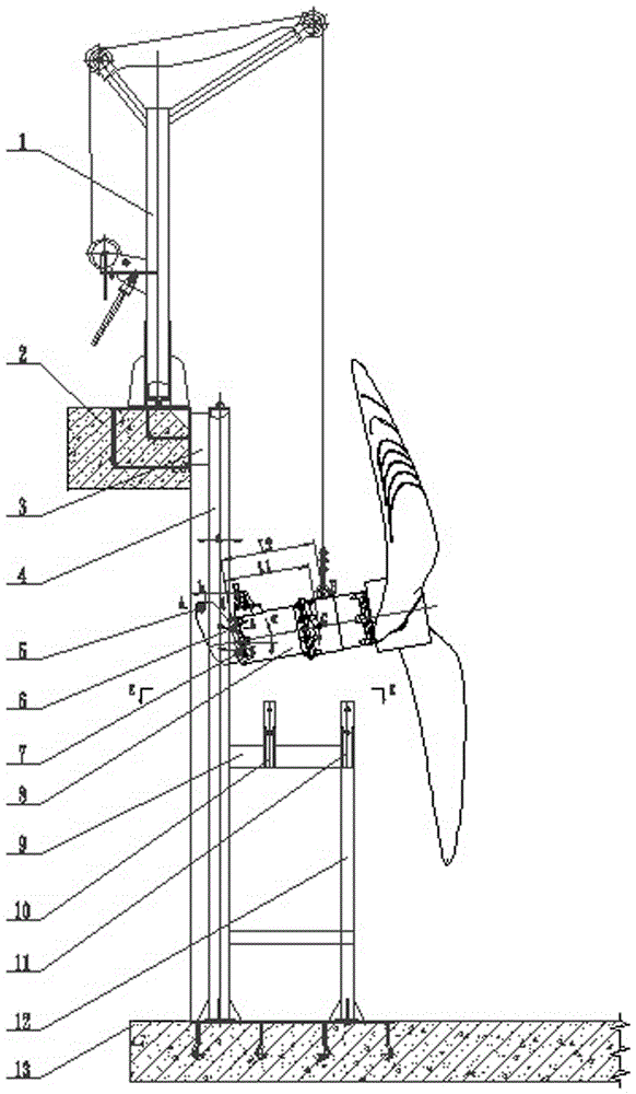
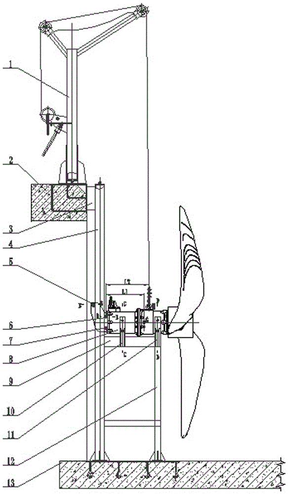
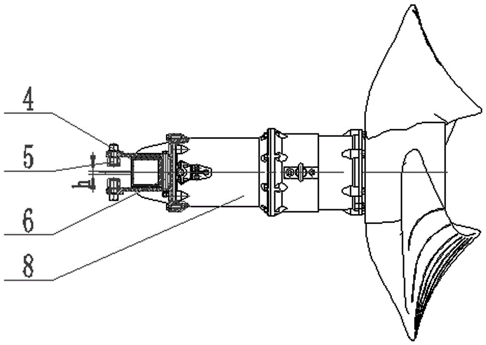
[0040] figure 1 , 2, 3, 4, 5, 6, 7, 8, and 14, a single-wheel rail sliding submersible flowmaker, which includes a lifting device 1, a pool surface installation base 2, a connecting plate 3, and a sliding guide rail 4. Limit pulley 5, rail pulley 6, load pulley 7, submersible thruster host 8, coupling seat beam 9, front coupling seat 10, rear coupling seat 11, coupling seat support 12, pool bottom installation base 13, lifting The device 1 is fixedly installed on the installation foundation 2 of the pool surface, and is mainly used for lifting the flow booster to move up and down along the guide rail. The sliding guide rail 4 is installed vertically, and the upper end is fixed to the connecting plate 3, and the connecting plate 3 is connected to the pool surface. The foundation 2 is pulled and fixed, the lower break is fixed to the installation foundati...


PUM


Abstract

The invention relates to a submerged flow pushing device based on rail-abutted single pulley sliding. A lifting device is fixedly mounted on a pool surface mounting base. A sliding guide rail is fixed to a connection plate and a pool bottom mounting base. A coupling base crossbeam is fixed to the sliding guide rail, and a coupling base support is fixed to the coupling base crossbeam and the pool bottom mounting base. A front coupling base and a rear coupling base are fixed to the coupling base crossbeam vertically at an interval. A spoiler is arranged at the rear end of a main body of the submerged flow pushing device. A lifting point is arranged at the front end of the main body of the submerged flow pushing device, and is positioned in front of the gravity center point of the main body of the submerged flow pushing device. The spoiler comprises two wings. A rail-abutted pulley and a loading pulley are arranged at the front end of a space between the spoiler wings, and a limiting pulley is arranged at the tail end of the space between the spoiler wings. A connective sliding cavity is formed by the two spoiler wings and the three pulleys. The sliding rail is embedded in the sliding cavity. The spoiler and the sliding rail are in a moving pair state, and the pulleys and the sliding rail are in a moving pair and rotating pair state. The spoiler, the pulleys and the sliding rail form a sliding structure and are in an embedded movement state.

Description

technical field [0001] The invention relates to a diving equipment, in particular to a single-wheel rail sliding type diving flowmaker. [0002] technical background [0003] In the sewage treatment industry, submersible flowmakers are widely used in anaerobic pools, anoxic pools and aeration tanks. Generally, the depth of the pool is about 5 to 7 meters. The submersible flowmakers normally work at a position 1.5 meters away from the bottom of the pool. It has the functions of mixing sewage, stirring sludge, promoting the flow of water medium, maintaining the flow velocity at the bottom of the pool ≥ 0.3m / s, preventing sludge settlement, and improving the efficiency of sewage treatment. Due to the high technical content and high import rate of this equipment, it has a great influence on the discharge of sewage effluent treatment standards, and the market usage is relatively large. Conventional submersible flowmaker equipment includes submersible flowmaker main engine, liftin...

Claims


Application Information

Patent Timeline
IPC IPC(8): C02F3/00
CPCC02F3/00C02F2203/006C02F2203/008C02F2303/14
Inventor 梅红霖辛健蒋文军鞠九华李晶
Owner 亚太泵阀有限公司
Why Eureka
Try Eureka