Batch grinding equipment for cutting edges of mechanical cutters

A batch grinding and cutting tool technology, applied in grinding/polishing equipment, metal processing equipment, other manufacturing equipment/tools, etc., can solve the problems of low grinding accuracy and low efficiency of grinding devices, so as to improve grinding efficiency and improve the overall The effect of working efficiency and reducing the probability of injury

Inactive Publication Date: 2021-06-29
孙莉新
View PDF12 Cites 0 Cited by
  • Summary
  • Abstract
  • Description
  • Claims
  • Application Information

AI Technical Summary

Problems solved by technology

[0006] Aiming at the above-mentioned defects in the prior art, the present invention proposes a batch grinding equipment for

Method used


Image

  • Batch grinding equipment for cutting edges of mechanical cutters
  • Batch grinding equipment for cutting edges of mechanical cutters
  • Batch grinding equipment for cutting edges of mechanical cutters

Examples


Embodiment 1

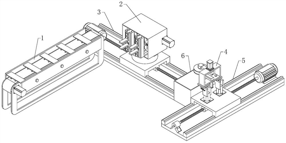
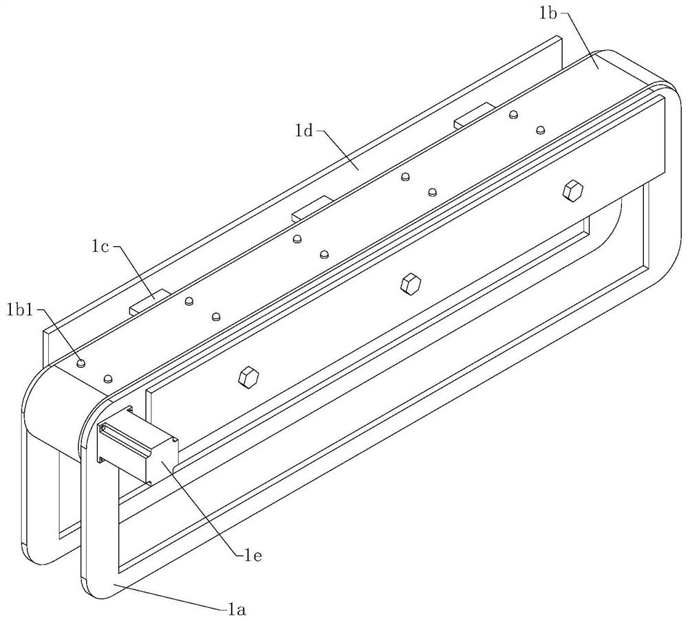
[0079] as 1 to Figure 10 As shown, a batch grinding equipment for mechanical knife blades includes a feeding device 1;

[0080] The gripping device 2 is arranged on one side of the output end of the feeding device 1, and the gripping end of the gripping device 2 faces a direction close to the feeding device 1;

[0081] The No. 1 mobile device 3 is arranged on one side of the output end of the feeding device 1, the clamping device 2 is fixed on the No. 1 mobile device 3, and the No. 1 mobile device 3 and the feeding device 1 are vertically distributed;

[0082] Grinding device 4, the grinding end faces the direction close to the feeding device 1;

[0083] No. 2 mobile device 5 is arranged on No. 1 mobile device 3 at an end away from feeding device 1, No. 2 mobile device 5 is vertically distributed with No. 1 mobile device 3, and polishing device 4 is fixed on No. 2 mobile device 5;

[0084] The collection box 6 is arranged between the No. 1 mobile device 3 and the No. 2 mobi...

Embodiment 2

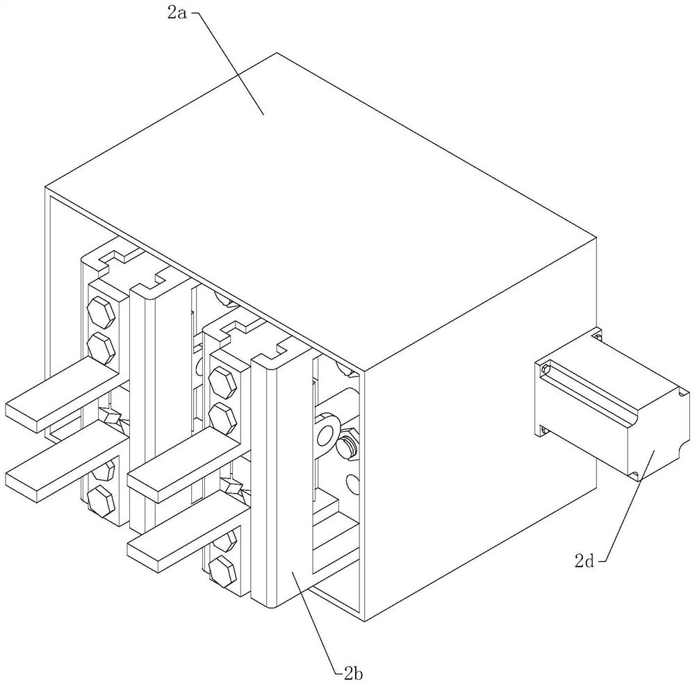
[0126] Compared with Embodiment 1, in this embodiment, as shown in 9, the grinding device 4 includes a grinding device housing 4a, which is in the shape of a rectangular sleeve as a whole, and the grinding device housing 4a is fixedly arranged on No. 2 mobile device 5. The grinding device There are through holes with the same position on the two parallel sides of the shell 4a;

[0127] Grinding machine 4b, the grinding end is arranged on the outside of the grinding device shell 4a and faces the direction close to the clamping device 2, and the other end is set inside the grinding device shell 4a, and the number of the grinding machine 4b is set to two and mutually in a mirror image distribution;

[0128] No. two cylinder 4c is fixed on the outer wall of the grinding device housing 4a, and the piston rod points to the inside of the grinding device housing 4a, and the end of the piston rod away from the second cylinder 4c is fixedly connected with the other end on the grinding ma...


PUM


Abstract

The invention relates to the field of cutting edge grinding, in particular to batch grinding equipment for cutting edges of mechanical cutters. The batch grinding equipment comprises a feeding device, a clamping device, a first moving device, a grinding device, a second moving device and a collecting box; the clamping device is arranged at one side of the output end of the feeding device, and the clamping end of the clamping device faces the direction close to the feeding device; the first moving device is arranged at one side of the output end of the feeding device, the clamping device is fixed to the first moving device, and the first moving device and the feeding device are perpendicularly distributed; the grinding end of the grinding device faces the direction close to the feeding device; the second moving device is arranged at the end, away from the feeding device, of the first moving device, the second moving device and the first moving device are perpendicularly distributed, and the grinding device is fixed to the second moving device; and the collecting box is arranged between the first moving device and the second moving device. According to the batch grinding equipment, automatic grinding work of the cutting edges of the mechanical cutters can be rapidly completed, manpower resource consumption is reduced, and meanwhile, the production efficiency of the whole equipment is improved.

Description

technical field [0001] The invention relates to the field of blade grinding, in particular to a batch grinding equipment for blades of mechanical knives. Background technique [0002] As a common cutting tool, knives have a wide range of uses, but they often damage the blade during use, resulting in a short overall service life of the knives. Therefore, most of the popular ones on the market are replaceable blades. In order to ensure the cutting efficiency of these blades, we often need to use a grinding device to grind them. [0003] Most of the common blade grinding devices on the market are single-sided grinding devices, which require manual grinding on both sides of the blade. This grinding method is not only inefficient, but also the grinding device can only grind one position of the blade during grinding. , It is necessary to manually adjust the grinding position continuously, the grinding accuracy is not high, and the blade grinding is uneven. [0004] As disclosed ...

Claims


Application Information

Patent Timeline
IPC IPC(8): B24B3/00B24B41/00B24B41/06B24B41/02B24B27/00B24B47/22
CPCB24B3/00B24B41/005B24B41/06B24B41/02B24B27/0076B24B47/22
Inventor 孙莉新
Owner 孙莉新
Why Eureka
Try Eureka