
Hybrid power system and working method thereof

A technology of a hybrid power system and a working method, which is applied in the field of hybrid power systems, can solve the problems of complex control methods and complex settings of the hybrid power system, and achieve the effects of simple control methods, avoiding thermal runaway or generating local hot spots, and simple system settings.

Inactive Publication Date: 2021-06-29
佛山市攀业氢能源科技有限公司
View PDF5 Cites 1 Cited by
  • Summary
  • Abstract
  • Description
  • Claims
  • Application Information

AI Technical Summary

Problems solved by technology

[0004] Therefore, the technical problem to be solved by the present invention is to overcome the defects of the existing hybrid power system with complex settings and complicated control methods, thereby providing a hybrid power system and its working method

Method used


Image

  • Hybrid power system and working method thereof
  • Hybrid power system and working method thereof

Examples


Embodiment 1

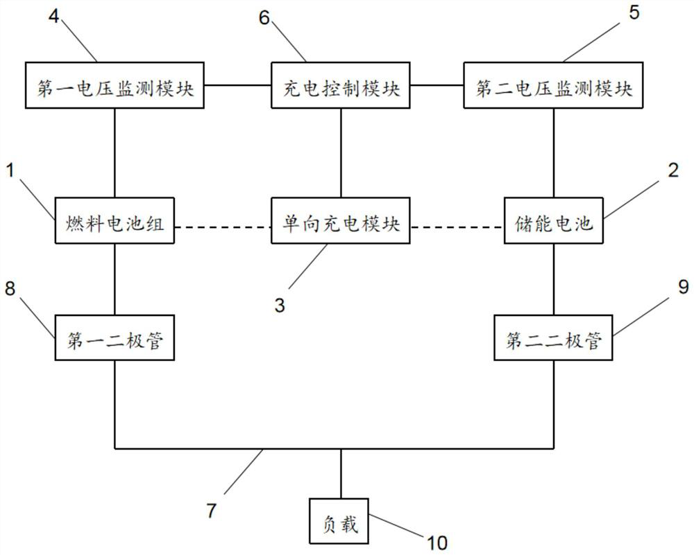
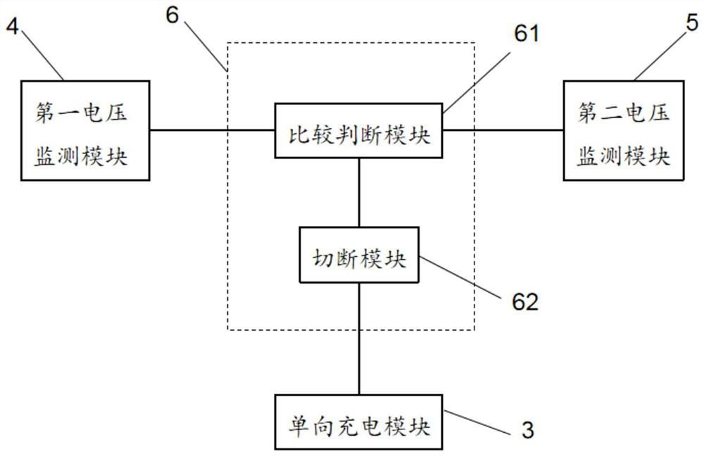
[0028] see figure 1, this embodiment provides a hybrid power system, including: a fuel cell 1 and an energy storage battery 2, the fuel cell 1 and the energy storage battery 2 are connected in parallel and are suitable for supplying power to a load 10; a one-way charging module 3, the The input end of the one-way charging module 3 is electrically connected to the fuel cell 1, and the output end of the one-way charging module 3 is electrically connected to the energy storage battery 2; the first voltage monitoring module 4, the first voltage The monitoring module 4 is electrically connected to the fuel cell 1 and is suitable for monitoring the voltage of the fuel cell 1; the second voltage monitoring module 5 is electrically connected to the energy storage battery 2 and is suitable for Monitoring the voltage of the energy storage battery 2; charging control module 6, the charging control module 6 is adapted to monitor the voltage according to the first voltage monitoring module...

Embodiment 2

[0037] This embodiment also provides a working method of a hybrid power system, which adopts the hybrid power system provided in Embodiment 1, and the working method of the hybrid power system includes the following steps:

[0038] The first voltage monitoring module 4 obtains the initial voltage of the fuel cell 1;

[0039] The second voltage monitoring module 5 acquires the initial voltage of the energy storage battery 2;

[0040] The charging control module 6 compares the initial voltage of the fuel cell 1, the initial voltage of the energy storage battery 2, and the charging cut-off voltage of the energy storage battery 2:

[0041] (1) When the initial voltage of the fuel cell 1 is equal to the initial voltage of the energy storage battery 2, the charging control module 6 controls the one-way charging module 3 to cut off the fuel cell 1 to the energy storage battery 2, the fuel cell 1 and the energy storage battery 2 supply power to the load 10 together;

[0042] (2) Whe...


PUM


Abstract

The invention provides a hybrid power system and a working method thereof.The hybrid power system comprises a fuel cell, an energy storage cell, a one-way charging module, a first voltage monitoring module, a second voltage monitoring module and a charging control module, wherein the fuel cell and the energy storage cell are connected in parallel and suitable for supplying power to a load; an input end of the one-way charging module is electrically connected with the fuel cell, an output end of the one-way charging module is electrically connected with the energy storage cell, the first voltage monitoring module is electrically connected with the fuel cell, and the second voltage monitoring module is electrically connected with the energy storage cell. According to the hybrid power system, self-adaption of working modes under different conditions is achieved, the control method is simple, system setting is simple, meanwhile, thermal runaway or local hot spot generation of the fuel cell due to the fact that the power generation efficiency is reduced due to the fact that the voltage of the fuel cell is too low is avoided, and finally the fuel cell is prevented from being damaged.

Description

technical field [0001] The invention relates to the technical field of clean energy, in particular to a hybrid power system and a working method thereof. Background technique [0002] Electric vehicles, that is, electric drive vehicles, have another name called electric drive vehicles. Generally speaking, electric vehicles use batteries as the energy source, and convert electrical energy into mechanical energy through controllers, motors and other components to control the current and change the speed of the vehicle. At present, lithium-ion batteries are gradually replacing lead-acid batteries as the main power source of electric bicycles due to their high specific energy and dynamic high-current response speed. Generally, the specific energy of lithium-ion batteries is 120Wh / kg-150Wh / kg. However, the battery life of lithium-ion batteries is limited. Generally, the driving range of lithium-ion batteries is generally 50km-60km. At the same time, the charging time is still r...

Claims


Application Information

Patent Timeline
IPC IPC(8): B60L50/75B60L53/00
CPCB60L50/75B60L53/00Y02T10/70Y02T10/7072Y02T90/14Y02T90/40
Inventor 施涛吴晓汶
Owner 佛山市攀业氢能源科技有限公司
Learn More