Automatic threading device, winding system and automatic threading method

An automatic threading and threading technology, applied in the directions of packaging, transportation, packaging, labeling, etc., can solve the problems of low degree of automation, inability to adapt to fully automatic winding, etc., to achieve a high degree of automation, improve processing efficiency, and improve utilization. Effect

Pending Publication Date: 2021-06-29
SUZHOU JIANGJIN AUTOMATION TECH
View PDF0 Cites 0 Cited by
  • Summary
  • Abstract
  • Description
  • Claims
  • Application Information

AI Technical Summary

Problems solved by technology

[0004] The existing perforation operation is realized by manual operation, the degree of automation is low, and it cannot meet the needs of fully automatic winding

Method used


Image

  • Automatic threading device, winding system and automatic threading method
  • Automatic threading device, winding system and automatic threading method
  • Automatic threading device, winding system and automatic threading method

Examples


Embodiment 1

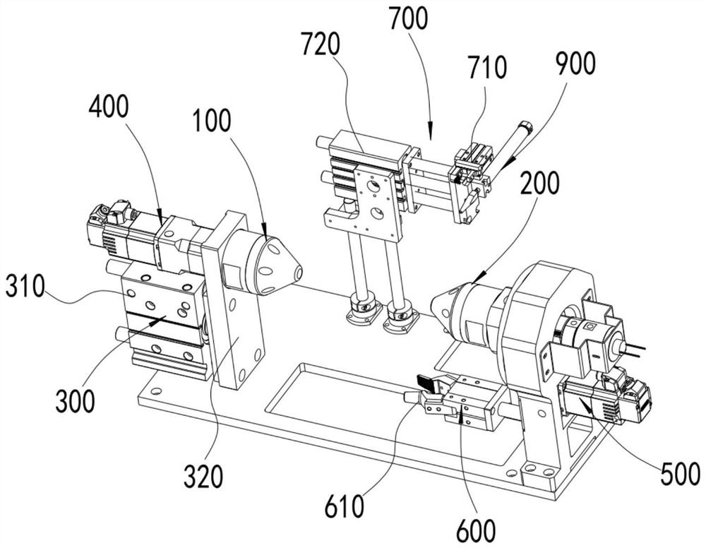
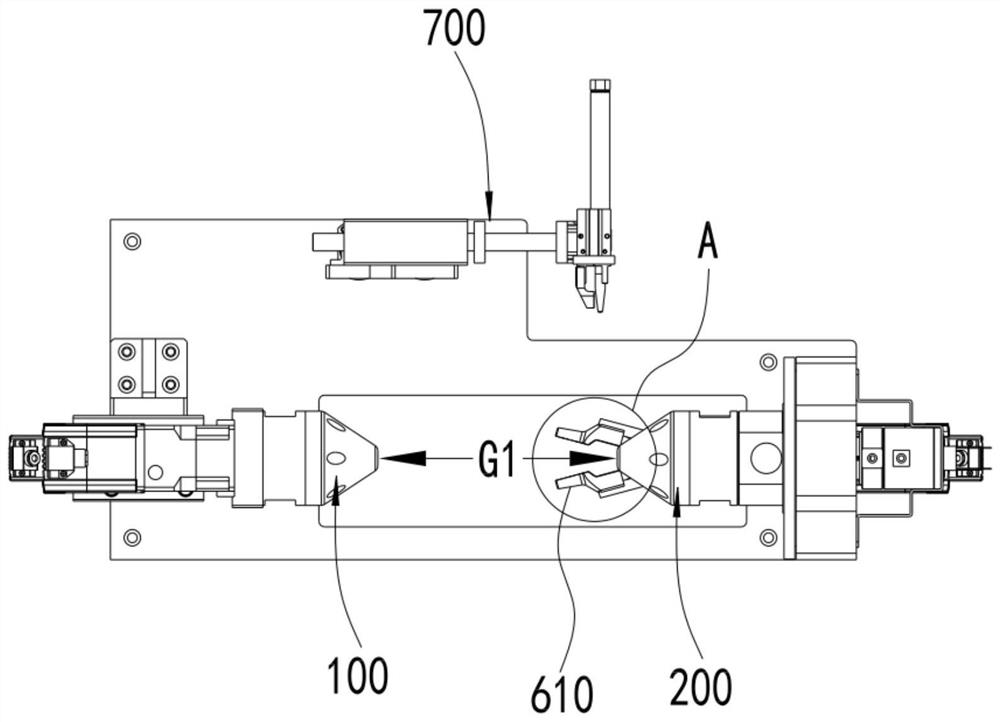
[0071] The thread end knotting device disclosed by the present invention will be described below in conjunction with the accompanying drawings, as shown in the attached figure 1 As shown, it includes a drive shaft 100 and a driven shaft 200 coaxially arranged on the placement table 1000 with gaps. The size of the word wheel is designed so that the I-shaped wheel can be suspended and fixed between them.

[0072] as attached figure 1 As shown, the driving shaft 100 and / or the driven shaft 200 are driven by the axial driving mechanism 300 to move axially, the driving shaft 100 is connected to the first driving mechanism 400 that drives its rotation, and the driven shaft 200 An automatic jaw 600 driven by the second drive mechanism 500 to revolve around the driven shaft 200 is arranged on the outer periphery, and the chuck 610 of the automatic jaw 600 faces the driving shaft 100 and extends to the end of the driven shaft 200 A certain distance in front, said distance is determin...

Embodiment 2

[0096] In the above-mentioned embodiment 1, the method of manual loading and unloading is adopted, but the weight of the full line wheel is relatively large, and it is inefficient and labor-intensive to manually load the material and fix the thread end on the thread end grasper, so it is more labor-intensive. The best way is to use automatic equipment for loading and unloading and place the thread end between the two jaws of the thread end gripper.

[0097] as attached Figure 11 , attached Figure 12 As shown, in this embodiment, the above functions are realized by the loading and unloading robot b. The wire wheel grabbing device b1 of the wire wheel, the moving mechanism b2 for driving the wire wheel grabbing device b1 to move, and the wire between the wire wheel and the wire pay-off frame e1 of the winding machine e before they are disconnected The wire end gripper b3 between the wire clamps.

[0098] Specifically, as attached Figure 13 As shown, the wire wheel grabbin...

Embodiment 3

[0110] In the above-mentioned embodiment 2, the wire between the full-line wheel and the pay-off frame e1 is manually cut off, or the gripper and the thread-cutting mechanism provided at the winding machine or the pay-off frame are used to realize the connection between the full-line wheel and the wire-cutting frame. The cutting of the wire between the pay-off frames e1.

[0111] as attached Figure 11 As shown, in this embodiment, the fuse of the wire and the clamping of the wire end on one side of the pay-off frame are realized by setting the automatic wire breaking mechanism d. Specifically, the automatic wire breaking mechanism d is set on the substrate c and is located between the placing table 1000 and the loading and unloading robot b, which is close to the placing table 1000 .

[0112] as attached Figure 16 As shown, the automatic disconnection mechanism d includes a mounting frame d100, and a fuse d200 is arranged on the vertical plate d110 of the mounting frame d100...


PUM


Abstract

The invention discloses an automatic threading device, a winding system and an automatic threading method. The automatic threading device comprises a bearing piece and a moving mechanism driving the bearing piece to move, wherein a first threading clamping jaw and a second threading clamping jaw which are located on the outer side of the bearing piece are arranged on the bearing piece; the included angle between extension lines of the first threading clamping jaw and the second threading clamping jaw in the length direction is an acute angle, the front ends of clamping heads of the first threading clamping jaw and the second threading clamping jaw face outwards, the opening and closing directions of the clamping heads are parallel; and a gap between the two first clamping heads of the first threading clamping jaw and a gap between the two second clamping heads of the second threading clamping jaw can be opposite in position and equal in height. According to the automatic threading device, the two threading clamping jaws are adopted, and a thread end can be inserted into a threading hole in a segmented mode; on one hand, the length of a silk thread penetrating into the threading hole can be effectively increased, and the problem that the thread end retreats from the threading hole in the winding process is avoided; and on the other hand, the several-times threading of two sections of relatively short silk threads is easier to realize compared with the threading of one section of relatively long silk thread, and the threading stability is higher.

Description

technical field [0001] The invention relates to the field of winding equipment, in particular to an automatic threading device, a winding system and an automatic threading method. Background technique [0002] The winding machine is a device that winds the wire on the I-shaped wheel. After the empty I-shaped wheel is installed on the winding machine, it is necessary to pre-wind the thread at the pay-off frame to the spool shaft of the I-shaped wheel for a certain circle. After several times, the winding machine can be started for subsequent winding operations. [0003] In order to ensure the stability of pre-winding, a hole is usually opened on the spool shaft, and the thread end is inserted into the through hole to a certain depth before pre-winding for a certain number of turns. [0004] The existing perforation operation is realized by manual operation, the degree of automation is low, and it cannot meet the needs of fully automatic winding. Contents of the invention ...

Claims


Application Information

Patent Timeline
IPC IPC(8): B65H67/04B65H65/00B65H67/08B65H67/06B65H69/04B65C9/18B65C9/40
CPCB65H67/0411B65H65/00B65H67/081B65H67/06B65H69/04B65C9/40B65C9/1876B65H2701/35
Inventor 陈中杰张文俊
Owner SUZHOU JIANGJIN AUTOMATION TECH
Why Eureka
Try Eureka