
Large bearing ring heat treatment clamp for heavy industrial machinery

A bearing ring and mechanical technology, which is applied in the field of heat treatment fixtures for large bearing rings used in heavy industry machinery, can solve problems such as uneven force on the pallet, side bending deformation and separation of the pallet, increase strength and toughness, and prevent side bending deformation , saving the use of the effect

Inactive Publication Date: 2021-06-29
廖加胞
View PDF6 Cites 1 Cited by
  • Summary
  • Abstract
  • Description
  • Claims
  • Application Information

AI Technical Summary

Problems solved by technology

[0002] Heat treatment refers to a metal thermal processing process in which the material is heated, kept warm and cooled in a solid state to obtain the desired structure and performance, which can greatly increase the strength and toughness of the workpiece. The large bearing ring is a relatively complex structure, For large-diameter thin-walled parts with relatively sharp changes in cross-sectional dimensions and thin-walled cutting edges, special fixtures are required to fix the bearing rings when heat-treating such large-scale bearing rings. In the prior art, pallets are often used. This method is used to carry the bearing ring, and a central rod is set in the center of the pallet to prevent the bearing ring from slipping off the pallet. Although this method can position the bearing ring and prevent the bearing ring from slipping off the pallet, it is difficult to balance the bearing ring on the pallet. The position on the pallet will lead to uneven stress on the pallet, which will easily cause the pallet to bend and deform during the heat treatment process, thereby damaging the equipment;
[0003] After retrieval, the Chinese patent No. CN103725862A is a large-scale bearing ring heat treatment fixture, which includes a bottom plate, the center of the upper surface of the bottom plate is vertically provided with a rotating shaft, the rotating shaft is rotatably installed on the bottom plate, and the side wall of the rotating shaft is provided with threads; the main shaft, the main shaft passes through The thread fits and installs on the rotating shaft; the guide sleeve, the guide sleeve is fixedly installed on the upper surface of the bottom plate, and is coaxially arranged with the main shaft. In the hole, and the tail of the strut extends to the outside of the guide sleeve; the support block, the support block is fixedly installed at the tail end of the strut; the joint bearing, the number of the joint bearing is the same as the number of the guide hole, and the circumferential direction is evenly distributed on the side wall of the main shaft. There is a connecting rod on the joint bearing, and the end of the connecting rod is rotatably hinged on the head of the strut. The invention drives the support block to press against the inner wall of the bearing ring through the rotation of the main shaft to realize the clamping function of the bearing ring. It can quickly fix and position the bearing ring, but there are still the following disadvantages: 1. In the heat treatment process of the large bearing ring, there is high temperature and thermal stress, and the support block and the inner wall of the bearing ring are squeezed for a long time, and the inner side of the bearing ring The contact surface between the wall and the support block is prone to deformation and causes the bearing ring to separate from the support block, which in turn causes the bearing ring to fall off from the fixture, resulting in a major production accident; Rotation requires a large or high-power motor to drive, and thus consumes a lot of energy. For this reason, we propose a heat treatment fixture for large bearing rings for heavy industry machinery to solve the above problems

Method used


Image

  • Large bearing ring heat treatment clamp for heavy industrial machinery
  • Large bearing ring heat treatment clamp for heavy industrial machinery
  • Large bearing ring heat treatment clamp for heavy industrial machinery

Examples


Embodiment Construction

[0023] The following will clearly and completely describe the technical solutions in the embodiments of the present invention with reference to the accompanying drawings in the embodiments of the present invention. Obviously, the described embodiments are only some of the embodiments of the present invention, not all of them.

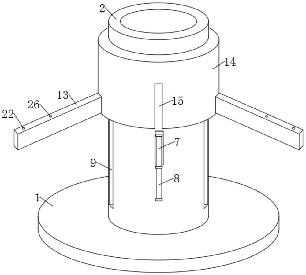
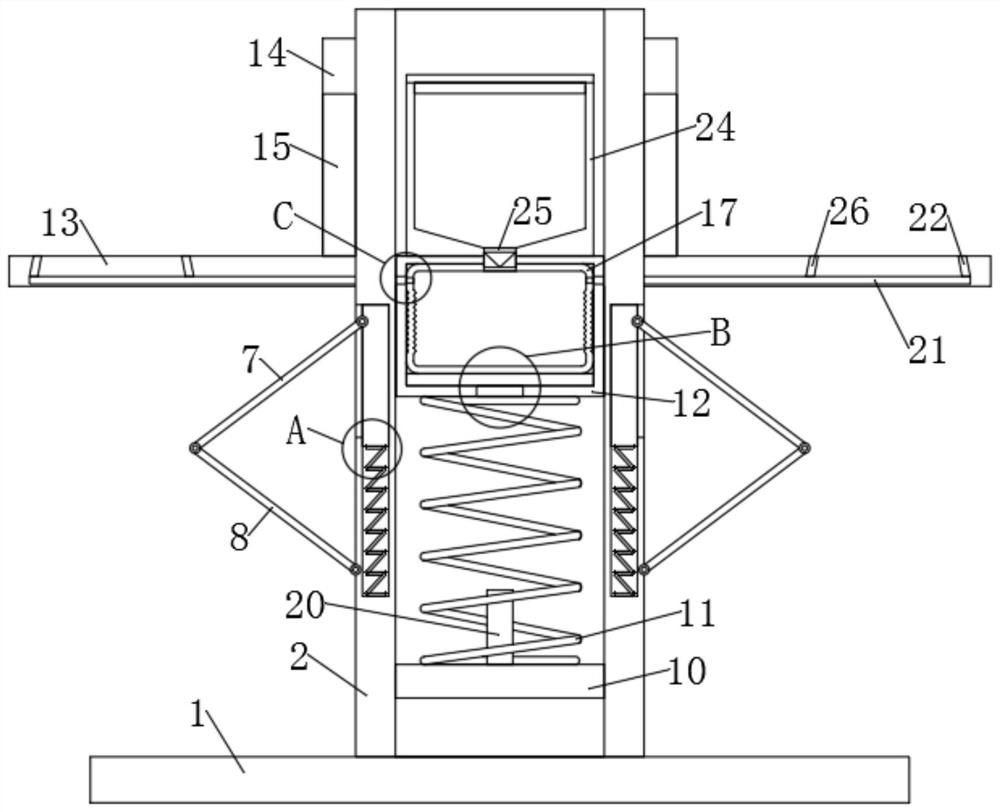
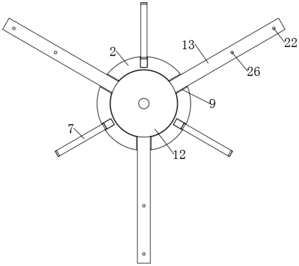
[0024] refer to Figure 1-6 , a large-scale bearing ring heat treatment fixture for heavy industry machinery, including a base 1, a central sleeve 2, and three brackets 13, the base 1, the central sleeve 2, and the brackets 13 are all made of high-temperature resistant materials, and the central sleeve 2 is fixedly connected On the side wall of the upper end of the base 1, three slide grooves 3 are respectively opened in the side wall of the central sleeve 2, and are equally distributed on the side wall of the central sleeve 2, and one end side wall of the three slide grooves 3 all runs through A first sliding port 4 is provided, and a slider 5 is slida...


PUM


Abstract

The invention discloses a large bearing ring heat treatment clamp for heavy industry machinery, and relates to the field of heat treatment equipment. The clamp comprises a base, a central sleeve and three supports, and the central sleeve is fixedly connected to the side wall of the upper end of the base. The base, the central sleeve, a sliding seat, the supports, a sliding sleeve and abutting rods are used in cooperation, when the clamp is used for carrying out positioning clamping during heat treatment on a large bearing ring, the bearing ring is hoisted to the supports, the supports are used for bearing the bearing ring, under the action of the gravity of the bearing ring, the supports and the sliding sleeve slide downwards, the abutting rods on the side wall of the central sleeve are embedded into embedding grooves in the side wall of the sliding sleeve, two abutting rods are unfolded outwards along with downward sliding of the sliding sleeve to automatically abut against the inner side wall of the bearing ring, the function of rapidly positioning and clamping the bearing ring under the action of the self weight of the bearing ring is achieved, the bearing ring can be automatically centered on the supports through the arrangement of the three abutting rods on the central sleeve, all the supports are evenly stressed, and the supports are prevented from being laterally bent and deformed.

Description

technical field [0001] The invention relates to the field of heat treatment equipment, in particular to a heat treatment fixture for a large bearing ring used in heavy industry machinery. Background technique [0002] Heat treatment refers to a metal thermal processing process in which the material is heated, kept warm and cooled in a solid state to obtain the desired structure and performance, which can greatly increase the strength and toughness of the workpiece. The large bearing ring is a relatively complex structure, For large-diameter thin-walled parts with relatively sharp changes in cross-sectional dimensions and thin-walled cutting edges, special fixtures are required to fix the bearing rings when heat-treating such large-scale bearing rings. In the prior art, pallets are often used. This method is used to carry the bearing ring, and a central rod is set in the center of the pallet to prevent the bearing ring from slipping off the pallet. Although this method can po...

Claims


Application Information

Patent Timeline
Patent Type & Authority Applications(China)
IPC IPC(8): C21D9/40C23C8/60C23C10/28
CPCC21D9/40C23C8/60C23C10/28
Inventor 廖加胞
Owner 廖加胞
Learn More